HYDRAULIC SYSTEM DEBUG
The Hydraulic System debug window is opened from the Debug menu of the Behaviors Debug window or from the SimObject Debug Menu itself. From this window you can get an overview of the components that make up the Modular Hydraulics System, as well as debug and edit them.
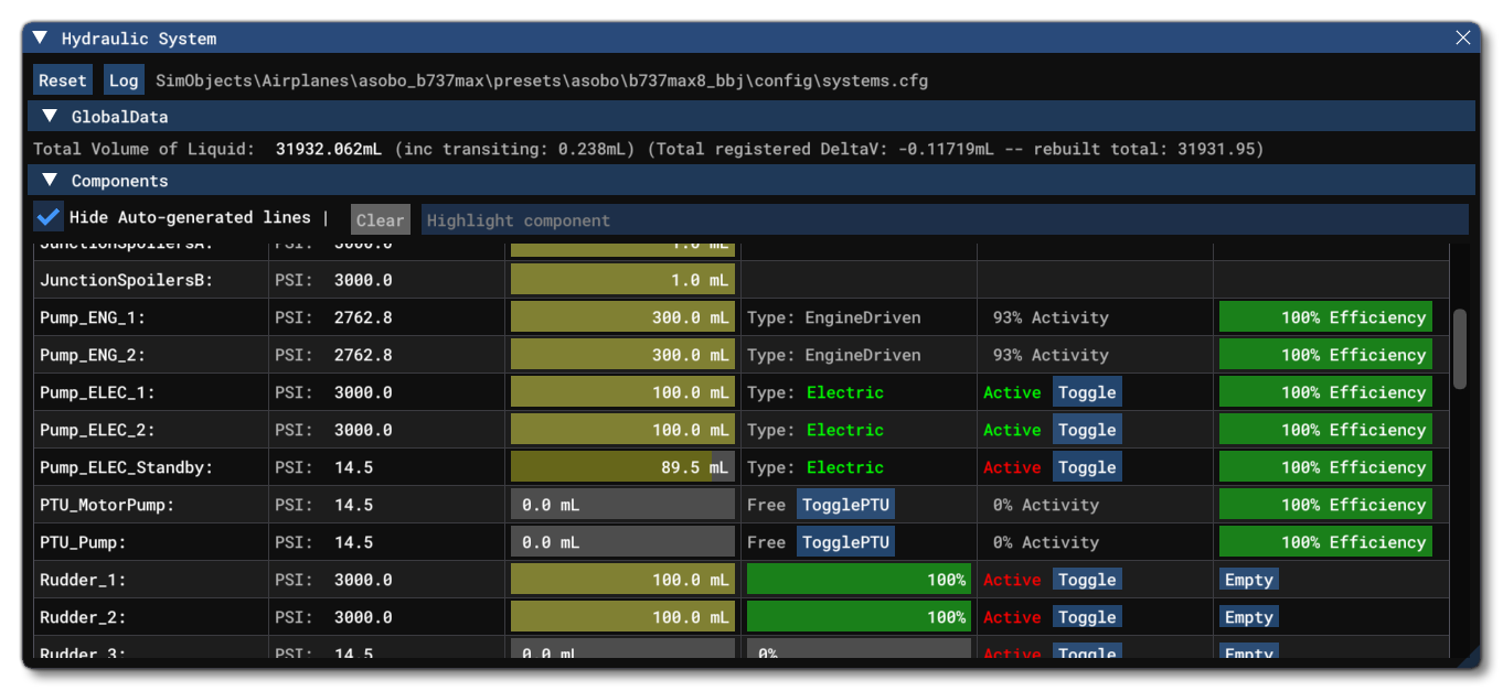
The top of this window has the following two buttons:
Reset: Clicking this button will reset the hydraulics system, emptying all components, refilling the tanks, and resetting the error log counter.Log: Clicking this button will log the current state of the hydraulics system to the Console, which can be filtered using the Message group filter to show only the hydraulics system output.

Below that you can also find the GlobaData section, which - when expanded - shows some global information about the system, as well as how many errors have been logged.

The rest of this window is taken up with a table that shows each of the components within the hydraulics system and different data points and options related to them. The top of the components section has an option to hide autogenerated lines (see here for more information: Automatic Generation of Lines) and also filter the list based on the text entered into the input field. Each component and it's information are listed below.
-
Reservoirs

Reservoir entries show the following information:
-
Name - The name of the reservoir component as defined in the CFG file.
-
Pressure - The current fluid pressure in the reservoir (in psi).
-
Fill Quantity - The quantity of hydraulic fluid in the reservoir.
-
Fill Quantity Control - This is a slider showing the percentage of the reservoir which is full, and you can click and drag on this to change the quantity of fluid in the reservoir in real-time and see the effect on other components.
-
-
Junctions

Junction listings show the following information:
-
Name - The name of the junction component as defined in the CFG file.
-
Pressure - The current fluid pressure in the junction (in psi).
-
Fill Quantity -The quantity of hydraulic fluid in the junction.
-
-
Pumps

Pump listings show the following information:
-
Name - The name of the pump component as defined in the CFG file.
-
Pressure - The current fluid pressure in the pump (in psi).
-
Fill Quantity - The quantity of hydraulic fluid in the pump.
-
Pump Type - The type of pump, either electric or engine driven. If the pump is electric, then it will be coloured as either green for powered or red for unpowered.
-
Pump Activity - For engine driven pumps this shows the power available to the pump, calculated from its internal pressure, expressed as a percentage. However, electric pumps are either shown as active (powered) or inactive (unpowered), which can be toggled for debugging using the
Togglebutton. -
Efficiency - The final bar shows the Wear and Tear on the pump components.
-
-
PTUs

PTU listings are shown as two sperate entries, with one being the "motor" (the drive) and the other the "pump" (the driven). Each one will show the following information:
-
Name - The name of the PTU component as defined in the CFG file, suffixed by the part of the PTU the listing references.
-
Pressure - The current fluid pressure in the PTU part (in psi).
-
Fill Quantity - The quantity of hydraulic fluid in the PTU part.
-
Clutch - The clutch is either shown as "Free" for both parts of the PTU if it's an unclutched unit, or "Driven" for the motor and "drive" for the pump. The clutch status can be toggled between clutched and unclutched using the Toggle button.
-
PTU Activity - This shows the power available to the PTU, which is calculated from its internal pressure, expressed as a percentage.
-
Efficiency - The final bar shows the Wear and Tear on the PTU components.
-
-
Actuators

Actuator listings show the following information:
-
Name - The name of the pump component as defined in the CFG file.
-
Pressure - The current fluid pressure in the pump (in psi).
-
Fill Quantity - The quantity of hydraulic fluid in the pump.
-
Integrity - The integrity bar shows the efficiency and ability to move for the actuator, and if you mouse over it, then a sub window will show at what point the actuator will stop working altogether.
-
Activity State - From here you can see if the actuator is active or not, and you can click the
Togglebutton to switch between active and inactive states. Note that this may not work, depending on the system setup and the model behaviors of the aircraft. -
Empty- Clicking this button will empty the actuator of all hydraulic fluid. Note that may only function for 1 frame before being reset, depending on the system setup and the model behaviors of the aircraft.
-
-
Lines

Line listings show the following information:
-
Name - The name of the line component as defined in the CFG file.
-
Pressure - The current fluid pressure in the line (in psi). This may be split into two parts if the line has a valve and the valve is closed. The first value is the pressure on the input side of the valve, and the second is the pressure on the output side of the valve.
-
Fill Quantity - The quantity of hydraulic fluid in the line. This may be split into two parts if the line has a valve and the valve is closed. The first value is the fluid quantity on the input side of the valve, and the second is the fluid quantity on the output side of the valve.
-
Valve - If the line has a valve associated with it, then the valve open percentage will be shown, and you can click and drag on the slider to change this. Note that you can mouse over this value to get the name of the associated valve, whether it's open or closed, and whether it is powered or not. You can reset this slider to the saved file value using the
Rbutton. -
Accumulator Status - If the line has an accumulator, this will be displayed as a dark blue bar representing the precharged gas, with a green bar overlay representing the hydraulic fluid stored in it. Note that this bar will never be "full" with the green bar filling the blue bar, as actuators are considered as being at capacity when they reach their normal pressure.
-
Related Topics