THE EDITION GIZMO
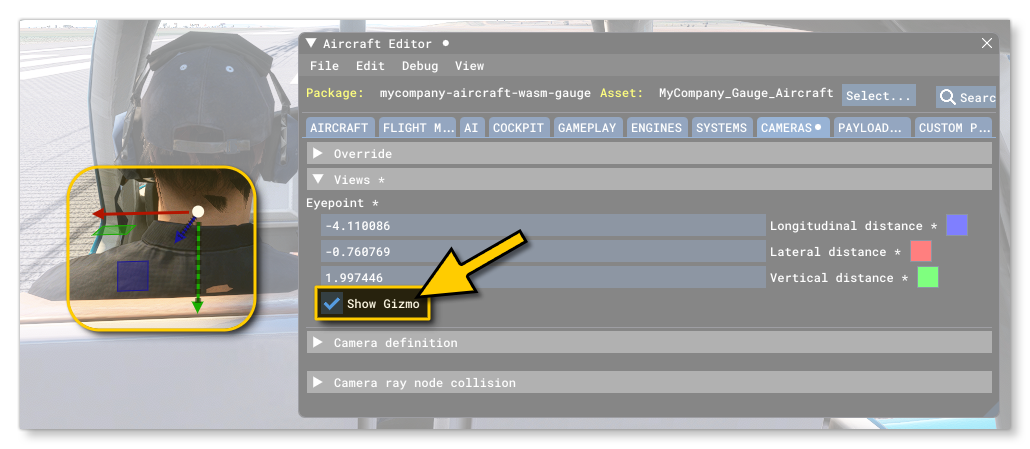
Many of the editors within the Developer Mode environment permit "live" edition of values using the edition Gizmo. This tool permits the placement of objects and nodes within the simulation directly, updating the values within the section of the editor that has enabled it. For example, in the SimObject Editor Camera section, you can use the Gizmo to define the position of the cockpit camera within the simulation itself:

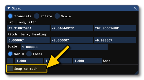
In most cases the Gizmo permits different kinds of edition depending on the mode selected, either translation, rotation, or scaling. The editors that use the Gizmo will have their own menu option - available from the Views menu - to open the Gizmo window, which will have the the following options (some options may be missing depending on the editor):

- Translate/Rotate/Scale: Select which kind of gizmo you want to use to apply changes to the element being edited.
- Lat/Long/Alt: Set the position using latitude, longitude and/or altitude for the element. These values will automatically change when manipulating the gizmo handles on the element(s) in the simulation, but you can also input values here manually.
NOTE: In the Scenery Editor, altitude may not be editable if the Snap To Ground option is checked in the element Properties.
- Pitch/Bank/Heading: These are used to set the rotation of the element along the X/Y/Z axis. These values will automatically change when manipulating the gizmo handles on the element(s) in the simulation, but you can also input values here manually.
- Scale: Set the size scale as a multiplier. For example, a value of 0.5 is half the base size, while a value of 2 would be double the size.
- World/Local: Selecting this will change the Gizmo UI to be based on the world location/angle or on the local location/angle.
- Group: This option is only available for the Rotate Gizmo and changes how grouped elements will be rotated. If this is checked, then 2 or more elements being rotated together will rotate around the common axis of the gizmo (the center-point between all elements), while un-checking this will cause all elements to rotate around their own center-points.
- Snap: This option permits you to enable/disable value snapping, as well as set the snap amount. For example, when scaling in the scenery editor, if you enable this option and set the value to 2, then the gizmo handles will only permit you to increment or decrement the object element scale in steps of 2.
As mentioned in the list above, each of the gizmos has different "handles" and "planes" so you can adjust the placement/rotation/scale within the simulation:

To use the different handles, simply click and hold the left mouse button on them and then drag. If you have selected multiple elements, then the gizmo will be placed in the approximate center of all of them and manipulating the gizmo with the mouse will move/rotate/scale all the selected elements together as one.
Finally, the following shortcuts are available when using the Gizmo:
-
When using the Translate gizmo in the Scenery Editor, holding down
Ctrl+Shiftthen clicking and dragging the gizmo will duplicate the currently selected object(s). -
If you position the mouse over the center point of the Gizmo and click the middle mouse button, you can swap between the different Gizmo types (translate, rotate, scale).
-
If you hold down the
Shiftkey while using any of the Gizmo controls the controls will react with more precision.
Snap To Mesh

Under some circumstance - for example, when editing a SimPropContainer - the Gizmo window will have an additional option: Snap To Mesh. When checked, the window then display a number of additional options that are designed to make it easier to align multiple objects perfectly based on the model vertices.

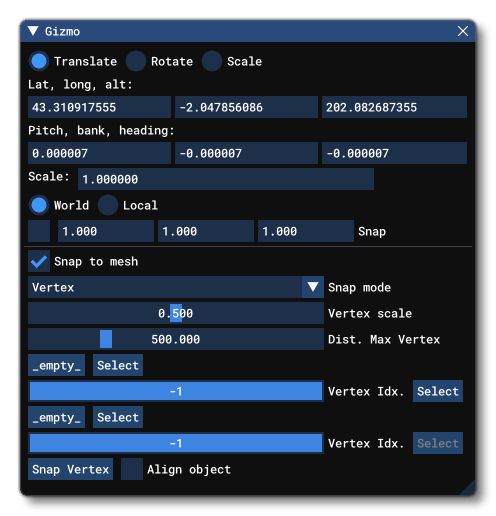
The new options visible when Snap To Mesh is enabled are as follows:
- Snap Mode: From here you can select the way that you want the meshes to snap together, either vertex, edge, or face.
NOTE: Currently only vertex snapping is available. - Vertex Scale: This option is simply to control the size of the debug visualization for the available vertex snap points.
- Dist. Max Vertex: This option is another debug visualisation that sets the maximum distance at which the debug graphics will be shown.
- Source Object
Select: Here you can select the object that you wish to snap, either by clickingSelectthen clicking the object you want to snap in the scene directly, or by clicking on the object button (flagged as_empty_to start with), which will then open a sub-window that lists all the applicable objects in the scene for you to select from. - Vertex Idx: This is the vertex that you wish to use as the snap location (it will snap from this vertex to the target vertex). You should not edit this directly, but instead click the
Selectbutton, then click on one of the highlighted vertices. - Target Object
Select: Here you can select the target object to snap to, either by clickingSelectthen clicking the object you want to snap in the scene directly, or by clicking on the object button (flagged as_empty_to start with), which will then open a sub-window that lists all the applicable objects in the scene for you to select from. - Vertex Idx: This is the vertex that you wish to use as the snap to location (the selected object vertex will snap to this vertex). You should not edit this directly, but instead click the
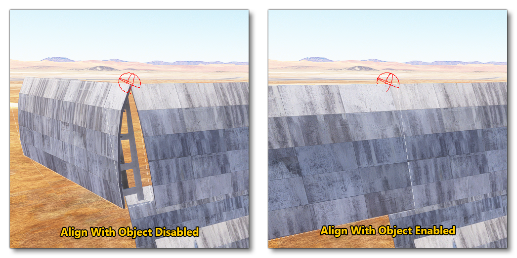
Selectbutton, then click on one of the highlighted vertices. Snap Vertex: This is the button that should be pressed once the snapping parameters have been set, as this button will perform the "snap" operation between the selected objects.- Align object: When checked, the object being snapped will align with the target object. When un-checked, this will not happen.
