GEOMETRY - FUSELAGE
NOTE: This page is currently WIP.
The fuselage can be set up using two different methods: using a generic fuselage shape, which is fine for simple aircraft and uses what is essentially a "cigar" shape for the main body, or using the modern geometry fuselage shapes, which permit the creation of a more precise fuselage shape. The modern geometry objects also permit the addition of fuselage parts like engine nacelles or floats, and even allow the creation of more exotic aircraft like the dual-fuselage F82 Twin Mustang.
Note that you can adjust the required parameters and then save in the SimObject editor, and the position of the different surface markers will change to reflect the new values, and the goal is to have the surface markers align with the actual shape of the fuselage (and fuselage elements).
NOTE: You can enable Live Edition and then select Auto Resync On Changes to see any changes that are made in the editor reflected in the simulation in real-time without the need to save first.
Before continuing, be aware that - unlike the aircraft wings and other geometry - the modern fuselage geometry objects don't need any of the generic fuselage parameters to be set up first, so if you are using the geometry objects, you can skip the generic fuselage setup (some parameters are used to set defaults, but they will need to be edited anyway and so it isn't really necessary to set them up).
Generic Fuselage Setup
The generic fuselage shape is essentially a "cigar" shape and will look like this initially:

To adjust the fuselage surface sensor positions and their dimensions to the visual fuselage of the aircraft model, you will need to edit the following parameters in the [AIRPLANE_GEOMETRY] section of the SimObject editor: Length, Diameter and Center (all in ft):

These parameters are named fuselage_length, fuselage_diameter, and fuselage_center_pos in the CFG file. As with the wings, you can use the simulation overlays to debug and position the fuselage if you don't have the exact values that you require:

The generic fuselage has 4 rows of surface sensors visible in the debug view which should be placed and visible along the model surface, in close proximity to the "shell" of the fuselage (although with the generic shape, some inconsistency is expected).
Advanced Fuselage Setup
To switch to using the modern fuselage geometry objects, the generic fuselage object first needs to be disabled by unchecking the enable_aircraft_geometry_fuselage option in the [DESIGN_ACTIVATION] section of the flight_model.cfg:

This will remove the generic fuselage from the simulation, and you can add a fuselage geometry object using the [OBJ_AIRGEO_FUSELAGE.N] section:

Initially you probably won't be able to see much in the debug view, so we strongly suggest that you first set some generic values just to get the approximate size and shape - specifically the size and element_number parameters. The size values are used to set the width (x), height (y), and length (z) of the fuselage form (in meters), and the element values are used to define how many surface sensors are going to be used for the definition. Essentially you want to create a cylinder that is the approximate length and width of the aircraft fuselage, eg:


It is important to note that more surface sensors will not improve the accuracy of the simulation. In general you want to aim for around 500 sensors for any fuselage object. For example, a small aircraft like the DA62 will use 540 sensors for it's main fuselage (), but then so will an airliner like the B737 Max. Adding more than this number of surfaces will not improve the aerodynamics simulation and will almost certainly affect the overall performance of MSFS 2024 as it processes the extra sensors for little to no gain.
Shaping The Geometry Object
Once you have roughed out the basic cylinder, it's time to shape or "sculpt" it to match the actual shape of the aircraft as close as possible. This is done using the following three parameters:

These parameters are used to scale the form of the fuselage sensors along the X-axis (lateral) and Y-axis (top and bottom). Essentially, the length of the fuselage is normalised 1, and then you add "points" from 0 to 1 defining the scale at that point, with the simulation adjusting the surface sensors to match this scale. You can do this by manually adding the points into the table associated with the parameter, however we strongly recommend that you use the Curve Editor instead. You can customise the graph view to suit the 0-1 scaling values and then add points into it to adjust the fuselage geometry, for example, the image below shows the curve used for the dim_scale_top parameter:

Once you have done this for the three parameters, you will have created the shape of the fuselage using the surface sensors:

You can then go ahead and repeat this process for any other fuselage elements.
It should be noted that there is one additional shaping parameter that can be used: dim_offset_middle. This parameter works like the other ones, as it is based on the normalised length of the fuselage geometry object and requires two values (offset in meters and position between 0 and 1). The values given here are used to offset the surface sensors along the length of the fuselage to create more complex and curved shapes, for example:

Setting Up The Aerodynamics
One of the major features of using the geometry objects for the fuselage is the ability to set up the aerodynamic properties of the "surfaces" that comprise the shape. A surface in this context is a plane generated from the surface sensor normal, and you can define the aerodynamics for these surfaces using the following parameters:
These parameters are explained in detail in the Note On Surface Cx, and so we won't go into that here. However we will quickly give a rough idea of how to apply some approximate values based on the fuselage shape and the measured drag coefficients shown below (note these are only some of the shapes that have pre-calculated values and you can find others on the internet):

The idea here is to look at your aircraft from the direction of one of the three axis, then check the shape you see against that given above, and then add the shown value into the corresponding axis of the parameter. Note that you are NOT adding it to the "look" axis, but the axis of the visible plane! So:
- Viewing from the back > X-axis plane
- Viewing from the side > Z-axis plane
- Viewing from the top > Y-axis plane
In the example below we are looking along the Z axis (from the back of the aircraft) and so the shape we see is that of the plane along the X-axis:
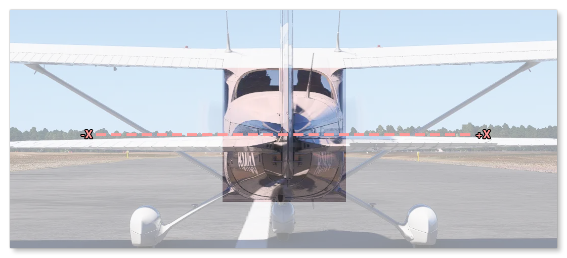
In this case the shape formed is closest to the "short cylinder" base shape (see the list above) and so we get an initial X component of 1.15, which can then be plugged into the X component of the surface_cx and surface_cx_normal parameters. You can then do the same for the Y and Z components of these parameters.
For the other parameters, unfortunately there is no "simple" way to get base values as they require complex computations done in an air tunnel or a fluid dynamics simulation. However, for the surface_cx_tangent you can start with value of 0.04 for each and then - through testing - tweak the components as necessary. For the surface_cx_efficiency, you can start with the following values:
- For X you can use the Oswald Efficiency Factor, or - if not known - set it to 1.0 initially.
- For Y you can use the Oswald Efficiency Factor, or - if not known - set it to 1.0 initially.
- For Z, set to 1.0.