LODs
In order to ensure optimal performance in Microsoft Flight Simulator for the models created for your add-ons (scenery, airports, aircraft, etc..) it is important to have a series of LODs created for each model. This is because levels of detail will be loaded into memory only when necessary, ie: only the data necessary to display a model will be loaded into memory at any time. To make sure this actually functions as designed by optimising performance, it is important that lower resolution LODs use less memory. Note though that the sum of the LODs in memory can still be relevant if an object is instantiated multiple times all around the player. In that case, multiple (or even all) LODs may be loaded and displayed at the same time, thus exist in memory at the same time, making optimising everything of paramount importance.
LOD files are stored as separate glTF files (one for each LOD) in the Models folder for the package. They are then referenced from the <model_filename>.xml using the <LODS> element. You can find an example of how to set this up here:
The most general rules of thumb for creating LODs - given the constraints that every LOD should reduce all Optimization Recommendations - would be:
- On each LOD, the number of vertices/faces should be around 50% of the previous LOD
- On each LOD, the number of materials used should be around 50% of the previous LOD
- On each LOD, the total texture memory (number of texels) used should be around 50% of the previous LOD
LOD Minsize Rules
The new LOD rules will be as follows, based in part on the minSize parameter of the <LOD /> element in the Model Definitions file:
- The last LOD's "minSize" is forced to 0.5% (this ignores the values set in the model XML).
- The last LOD's "maxVertices" is 150.
- The second-to-last LOD's "minSize" is forced to at least 1% (this ignores the values set in the model XML).
- The second-to-last LOD's "maxVertices" starts at 300, scaling up with the "minSize".
- At a "minSize" of "100%", "maxVertices" is 250,000.
- Limits scale up with the "minSize" above 100%: at 150%, "maxVertices" is approximately 480k.
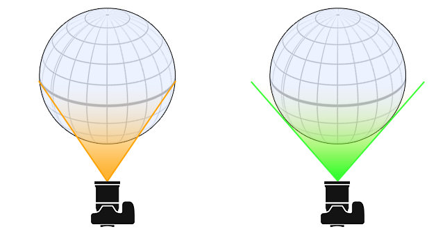
The "minSize" is the minimum size on screen of the bounding sphere of the object within the camera view - as a percentage - before a LOD model is considered for display. In the image below, we show how this is currently computed (in orange) and how this will be computed when the new LOD limit rules are enforced (in green):
The following graph gives a more mathematical representation of what's happening:
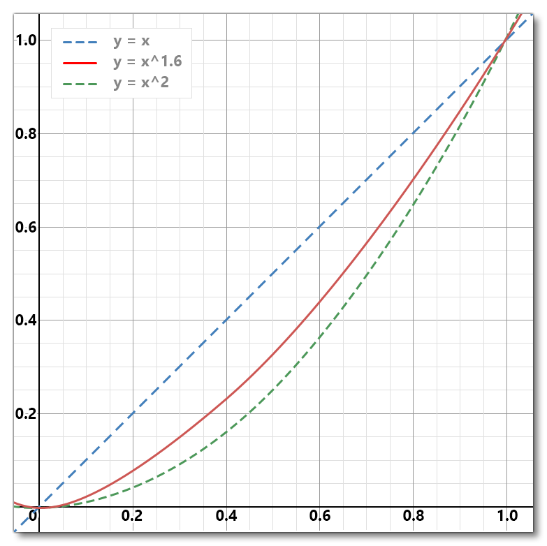 This graph demonstrates the following:
- The x-axis represents the model's current size on screen (where 1 = 100%).
- The y-axis is the resulting minimum for a given statistic.
- Below 1% size on screen (y <= 0.01) the maximum for a given statistic is hardcoded:
- Vertices: 150
- Draw count: 2
- At 1% size on screen (y = 0) the maximum number for a given statistic is hardcoded:
- Vertices: 300
- Draw count: 2
- Above 1% size on screen, the statistic follows the described curve, which goes through a size on screen of 1, where the maximum number for a given statistic is hardcoded:
- Vertices: 250000
- Draw count: 500
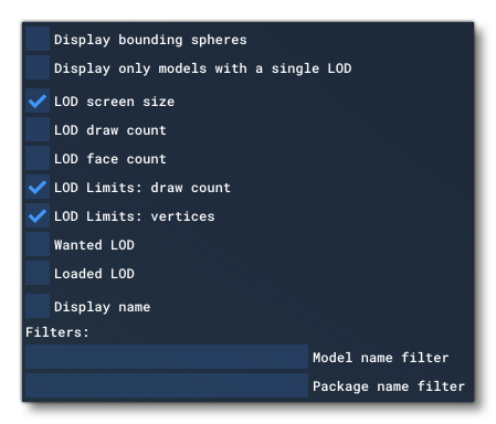
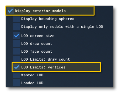
To be able to see what these limits mean within the simulation, you can use the various debug options available from the Debug LODs window, specifically the LOD Limits: draw count and LOD Limits: vertices options, although the others can also be useful:
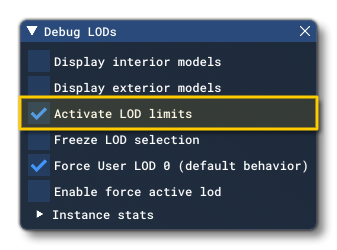
 It is also possible to enable/disable this new LOD system by checking the Activate LOD Limits option:
 This should be done before you start any flights, but if you enable/disable this option during a flight, you will have to exit the flight, wait 20 seconds, then start a new flight, to see any effect. Also note that the The Statistics Profiler window now also has extra options available to help debug the different LOD values.
How To Find Bad LODs
The instructions below are a basic guide on how to check the LODs for an asset based on these coming changes:
- Set your desired graphics quality from the Microsoft Flight Simulator options ("High" is recommended).
- Open the Debug LOD window, and check if "Activate LOD limits" is active. If it is, then you have to do the following:
- Disable "Activate LOD limits".
- If in a flight, go to the main menu, then wait 20 seconds before continuing.
- Load a flight at your preferred location.
- Now choose your preferred debugging method:
- Using the Debug LOD window:
- Check the "LOD Limits: vertices" checkbox
- Any model display that colors red means the currently active LOD will be culled under the new system. If a lower res LOD exists, it will switch to that, otherwise it will disappear completely.
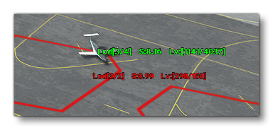
- Check the "LOD Limits: vertices" checkbox
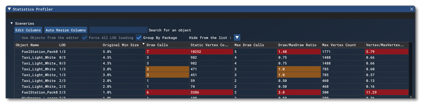
- Using the Statistics Profiler tool:
- Click the "Edit Columns" button and select these columns: LOD, Draw Calls, Static Vertex Count, Original Min Size, Max Draw Calls, Draw/MaxDraw Ratio, Max Vertex Count, Vertex/MaxVertex Ratio.
- Make sure the "Use Objects From Editor" checkbox is disabled (to be able to view independent model stats).
- Any cell that appears in RED (over the limit) or ORANGE (close to the limit) is a value that needs to be optimized.
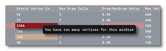
You can also mouse over the LOD entries flagged in red or orange to get an idea of what the issue is:
- Using the Debug LOD window:
General Recommendations
The following are some general recommendations that should be considered when creating model assets:
- We suggest that you create at least 4 LODs.
- In general, we recommend tweaking your LoDS in the "high" quality setting, which is neutral for LOD selection (meaning a LOD with 50% "minSize" will switch at 50% size on screen), and reduces the quality of only some textures.
- You should try and share textures between different models and model LODs.
- Remove textures you may not need at a distance, such as a normal map, and try very hard to avoid creating extra textures at a smaller resolution, this will just increase total memory usage. Prefer simply removing textures whenever possible.
- Use appropriate texture resolutions for your textures. It is usually not necessary that all textures in a material have the same resolution.
- Use metallic/roughness/… material settings instead of textures when possible.
- Every LOD should further reduce most - if not all - of its Optimization Recommendations if possible. The main considerations are texture memory used, the number of faces, and the number of draw calls. Typically, the number of vertices is at least halved with every LOD.
- Minimize skinned mesh usage. In Microsoft Flight Simulator, compared to regular objects, they consume a significant amount of CPU and memory, so use them only if mesh deformation is necessary. Skinning can often be avoided on lower resolution LODs. Also note that when a skinned mesh is moved with bones that are somewhere else completely in the hierarchy, you can have an issue where the skinned mesh disappears when looking at it because the bounding box used for camera frustum culling is in a completely different location from the vertices. To avoid this, make sure that the skinned mesh node itself is part of the hierarchy, such that the bounding box moves with it whenever possible.
- To make sure the last LOD is useful, the second-to-last LOD should have a "minSize" of at least 1%, but preferably be higher.
- The last LOD should have approximately 100 triangles, 1 material and no textures. Also note that:
- Since there are many objects far away, reducing them to one draw call is important.
- Its "minSize" property is ignored, it is always set to zero.
- If you do need a partially emissive or metallic last LOD, consider using a very small texture rather than creating a second material.
- You are not forced to keep the same node/instance structure in all LODs.
- Reducing the number of vertices and draw call on each LOD will bring you to a point where the instances could be merged together, and - if possible - they should be.
- Low poly LODs often do not need a texture at all, and you can simply use the vertex color (this is essentially a "free" way to color a model because of the single-vertex format.
- Prefer low-resolution textures for LODs below the approximate 5% "minSize", eg: try to keep this as 64x64px or smaller.
- If a model has lights, all its LODs will also need lights, otherwise you will see the lights "pop" into the scene as the LOD changes.
- All scenery model LODs, with the exception of objects that aren’t important for collision, need colliders. You should prefer using the collision shapes - rectangle, cylinder, sphere - over collidable materials. This is explained in more detail here: Collision Handling
Instancing And Flattening
One feature of creating a model as efficiently as possible is the use of instances to create "clone" objects within the model that will be rendered as a single batch and also be stored as a single object in memory, reducing the GPU overhead required to render it in the game. This sounds great, but comes with a trade-off as each instanced object will require it's own node in the model hierarchy, which in turn will require additional CPU processing. So, when dealing with different LODs, it is often worthwhile using instances on LoD0 and LoD1, but then flattening the model for the higher LODs. Flattening the model will greatly reduce the node count and combine everything into a single mesh, which may be more appropriate and give better performance at higher LODs.
Aircraft LODs
In order to ensure optimal performance - especially on the Xbox platform - it is important to have a series of LODs created for each aircraft. These should follow the general guidelines explained above, however we have prepared additional information relevant only to aircraft which can be found on the following page:
NOTE: The player aircraft will always be rendered using LOD0, regardless of how far from the camera gets. This behaviour can be temporarily disabled using the Force User LOD 0 option.
Airport And Scenery LODs
An airport can contain many models, and as such it is effective to group several objects together, to try and reduce the number of draw calls - especially when you take the Xbox target into consideration as it requires highly optimised assets. However - depending on the location - this shouldn't be done for very large areas and/or very high-poly meshes, as you will then not fully benefit from LOD and camera frustum culling when closer to the object.
NOTE: LODs can be debugged from the Debug LODs window, available from the DevMode Options. It will show various overlays to help debug the different LOD levels for the objects in a scene, and can also be used to force LOD levels to permit you to see them in the simulation.
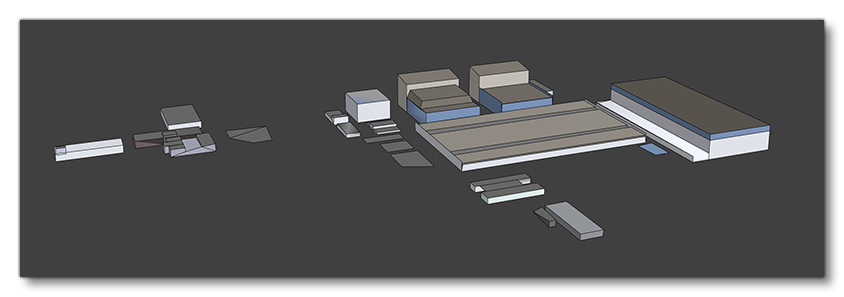
Below we show an example of an airport as it goes through the different LOD levels. Note that the first LOD has very detailed geometry with multiple textures, then we decrease the face count after LoD0 and remove textures, replacing them with vertex color. After LoD3, the textures are duplicated and reduced to 64*64px.
LoD0
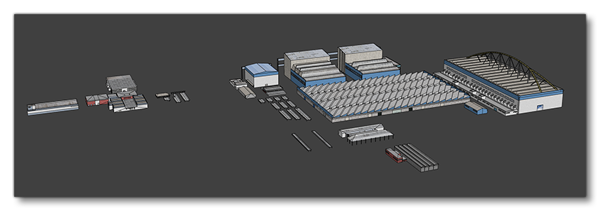
- minSize 150%
- 8632 faces
- approx. 15 materials
LoD1

- minSize 60%
- 3712 faces
- approx. 12 materials
LoD2
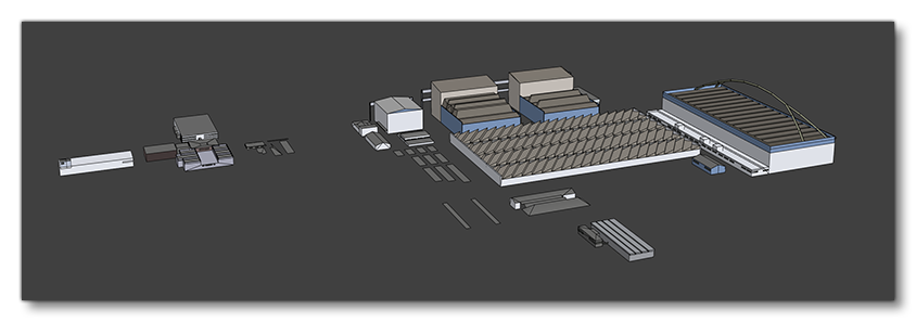
- minSize 15%
- 2063 faces
- 2 materials
LoD3
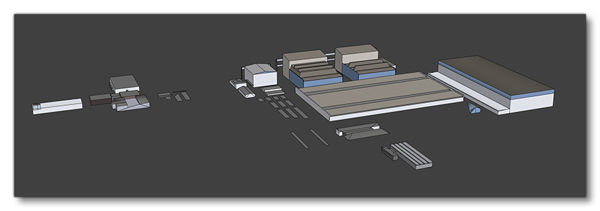
- minSize 7%
- 699 faces
- 1 material
LoD4
- minSize 3%
- 319 faces
- 1 material
LoD5
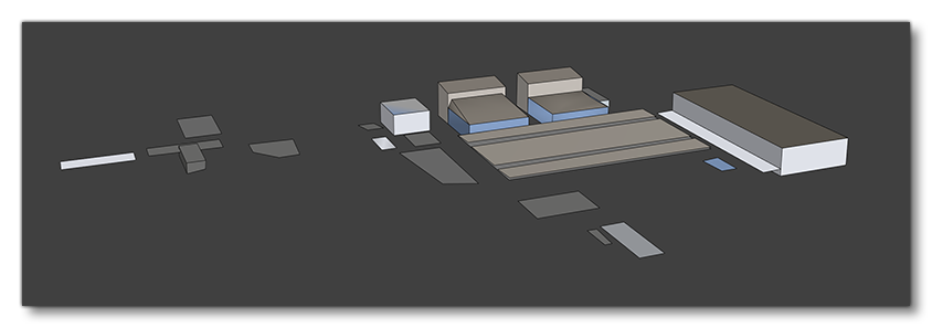
- minSize 1%
- 113 faces
- 1 material
LOD Animation
If you have any animated scenery elements it should be noted that the Microsoft Flight Simulator engine will perform some optimisations on them based on their size on screen and distance from the camera. What this means is that:
- As objects get further from the camera, animations will begin to "frame skip" and instead of updating every frame, they will update every N number of frames (the exact value depends on the distance). So, a 100 frame animation may play 1 animation frame every simulation frame up close, but then play 1 animation frame every five simulation frames when far away (frames are interpolated so it would play frames 1, 5, 10, 15, etc...).
- When the object is considered as less than 1% of the screens size then the animation will not be shown and the object will appear static.
The values used for these optimisation are based on the bounding sphere of the object which is calculated automatically by the engine based on the object mesh.
Now, for most objects this is fine and not really an issue, but if you have a large object with obvious animations then it can become problematic. To resolve this, we suggest that when making the object mesh you add an "invisible" box or sphere mesh to the object that is much larger than the object itself and export the object with this invisible mesh (for all LODs). The Microsoft Flight Simulator engine will then use this invisible part of the mesh to calculate the bounding sphere, meaning that the animation optimisations will not be applied until the object is much further from the camera.