SCENERY OBJECT DEFINITIONS
The <scene_filename>.xml file should be formatted as follows:
<?xml version="1.0" encoding="UTF-8"?>
<FSData version="9.0">
    <SceneryObject [attributes]>
        <!-- OBJECT PROPERTIES HERE -->
    </SceneryObject>
    <!-- FURTHER SCENERY OBJECTS HERE -->
</FSData>
Within the <FSData> element you would list all the different scenery objects you want to include in the package between opening and closing <SceneryObject> elements.
<ProjectedMesh>
This element is used to add a ProjectedMesh Object to a scene, although it can also be used to add a projected mesh object to an airport by adding it as a sub-element of <Airport>. Each projected mesh element requires a <SceneryObject> sub-element to define the object that belongs to it. The element has the following attributes:
| Attribute | Description | Type | Required |
|---|---|---|---|
priority |
This option sets the render priority for the projected mesh object. The default render priority is 0, which for most cases is fine. However, if you have overlapping meshes and want one to render over another one, then you will need to change this value to make it a higher or lower priority. Higher priority values will render over lower priorities, for example, a mesh with priority 1 will render over one with priority 0, which in turn will render over one with priority -1. Note that the engine cannot guarantee the render order for meshes with the same priority, so if you need something to always render over or under something else, you need to set this value. | Integer | No |
| drawOrder |
This option permits you to place meshes into the render hierarchy so that they are drawn under or over different elements. To use this attribute, you must supply one of the given strings, and the projectd mesh will be rendered after the given element has been rendered but before the next element (the element strings are listed in render order). For example, if you select "MARKING", then the projected mesh will be rendered over Aprons, Taxiways and Runways, but under Markings, Runway Markings and Marking Text. |
String (listed in order of rendering):
|
No |
surface |
This option permits you to select from a list of default surface types that can be applied to the projected mesh. These surfaces will be merged with the mesh texture to add further visual variety and better integrate the mesh with the terrain and surrounding elements. |
String:
|
No |
groundMerging |
Set this attribute to "TRUE" to have the projected mesh object be merged with the underlying ground, or set it to "FALSE" otherwise. You can see a visual example of this effect here: Ground Merging | Boolean | No |
<SceneryObject>
This element is used in multiple different places to add a scenery object to the sim. This element is explained in full along with its different attributes here: <SceneryObject>.
This element can contain one or more of the following sub-elements, and for scenery objects this will usually be at least <LibraryObject /> and <AttachedObject> (click the links below for more information on each element):
<BiasXYZ /><NoShadow /><HideOnTIN /><NoSnow /><Beacon /><Effect /><GenericBuilding><LibraryObject /><VisualEffectObject /><Trigger><Windsock><WorldScript /><SimObject /><AttachedObject>
It should be noted that the <AttachedObject> element should always be defined last.
<Polygon>
This element can be used to define a polygonal surface in a scene. It has multiple possible uses, for example:
- flatten terrain
- exclude auto-generated buildings
- force or exclude vegetation
- change vegetation type
- specify airport zones (changes the type of auto-generated buildings)
- apply a material to the ground
- add or remove water
This element can have the following sub-elements, which are required to define the polygon shape:
The polygon object will need at least 3 <Vertex /> definitions to be valid, and has the following attributes:
| Attribute | Description | Type | Required |
|---|---|---|---|
altitude |
The altitude of the polygon object, in meters | Float | Yes |
<Attribute />
This element is used within the <Polygon> object - sometimes multiple times - to define the features of the polygon. The element is self-closing and has the following attributes:
| Attribute | Description | Type | Required |
|---|---|---|---|
name |
The name of the attribute that is being added to the polygon object. You may include multiple <Attribute /> tags in a single polygon definition if it requires multiple attributes. See the page on Polygon Objects for more information on the attribute types. You can find an example of a polygon using multiple attributes here. |
String |
Yes |
GUID |
A GUID-formatted string to identify the attribute. | ||
type |
The type of value to be expected for the attribute. | ||
value |
The value for the named attribute. |
The table below shows the possible name attributes and their corresponding types and values:
name |
Description | type |
value |
|---|---|---|---|
| Version | A version number for the polygon. | STRING | A version number |
| UniqueGUID | The GUID-formatted Instance ID unique to the specific instance of the polygon object placed within the simulation. | GUID | GUID String, eg: "{6A44EFFC-195D-4E43-A2B2-62B0E285062A}" |
| FlattenFalloff | This sets the distance around the polygon which will be "feathered", smoothing the difference in altitude between the polygon terraformer and the surrounding terrain. | FLOAT32 | A value in meters. |
| FlattenMode | Sets whether the polygon should flatten the terrain it is placed on or not. | UINT8 | Integer, either "0" (enabled) or "1" (disabled) |
| ExcludeDetectedBuildings | Convert the polygon into an exclusion polygon which will exclude buildings created algorithmically from the aerial image data. | UINT8 | Integer, either "0" (false) or "1" (true) |
| ExcludeOSMBuildings | Convert the polygon into an exclusion polygon which will exclude buildings created from the data supplied by Open Street Maps. | UINT8 | Integer, either "0" (false) or "1" (true) |
| ExcludeMSBuildings | Convert the polygon into an exclusion polygon which will exclude buildings generated from open-source data for North America that comes from Microsoft. | UINT8 | Integer, either "0" (false) or "1" (true) |
| ExcludeTIN | Convert the polygon into an exclusion polygon which will exclude the TIN data streamed from Bing Maps, which may include buildings as well as other things. | UINT8 | Integer, either "0" (false) or "1" (true) |
| ExclusionFlags | A single value used to represent multiple possible exclusions for the polygon, summed together. | UINT32 |
Intger, a combination of the following (summed together):
|
| BuildingOnTIN | This can be used when you have excluded TIN data, but want to still have TIN generated buildings present. | UINT8 | Integer, either "0" (false) or "1" (true) |
| ForceDetectedBuilding | This option can be used to force the rendering of detected buildings for an area. | UINT8 | Integer, either "0" (false) or "1" (true) |
| BiomeName | This option permits you to select a different biome to be used for the vegetation within the polygon area. Note that when this attribute is included, any Material you have defined will no longer be shown. | STRING |
String to define the biome, one of the following:
|
| VegetationScale | This sets the scale of the vegetation within the polygon. | UINT32 | A value between 0 and 255, mapped to a scale of 0 and 1, respectively. |
| VegetationDensity | This sets the density of vegetation within the polygon. | UINT32 | Value between 0 and 62, where 31 is 100%, 0 is 0% and 62 is 200%. |
| VegetationFalloff | This sets the distance around the polygon in which the vegetation will be "feathered" between the edge and the surrounding terrain. | FLOAT32 | Value is in meters. |
| TreeBrightnessFactor | This setting is for changing the brightness of the vegetation color. | UINT32 | Value between 0 and 255, where 127 is 100%, 0 is 0% and 255 is 200%. |
| MaterialGUID | The GUID-formatted ID unique to the material to use with the polygon object. | GUID | GUID String, eg: "{6A44EFFC-195D-4E43-A2B2-62B0E285062A}" |
| MaterialTiling | This sets the tiling scale for the texture used by the material. | FLOAT32 | Value is in meters. |
| MaterialFalloff | This sets the distance around the polygon in which the material will be "feathered" to smooth the transition between the polygon material and the terrain. | FLOAT32 | Value is in meters. |
| MaterialRotation | This sets the angle at which the material texture will be rendered. | FLOAT32 | Value between 0 and 6.283185 (angle expressed in radians). |
| MaterialOpacity | This is for changing the transparency of the material. | UINT8 | A value between 0 and 255, mapped to a scale of 0 and 1, respectively. |
| MaterialColoration | This permits you to add a colored "tint" to the material. Setting the RGB values to (0, 0, 0) will remove all tinting. | UINT32 |
An unsigned integer that can be represented in hexadecimal with the format "RRGGBBAA". EG:
Note that the alpha component is always 255.
|
| Layer | This option sets the render priority for the polygon. The default render priority is 0, which for most cases is fine. However, if you have overlapping polygons and want one to render over another one, then you will need to change this value. | UINT32 | A render priority value. Higher priority values will render over lower priorities, for example, a polygon with priority 1 will render over one with priority 0, which in turn will render over one with priority -1. Note that the engine cannot guarantee the render order for polygons with the same priority, so if you need something to always render over or under something else, you need to set this value. |
| IsWater | Selecting this option tells the simulation that the polygon is defining an area of water. | UINT8 | Integer, either "0" (false) or "1" (true) |
| WaterType | Sets the type of water that you are defining with the polygon. | UINT32 |
Integer, where:
|
| IsWaterExclusion | Selecting this option tells the simulation that the polygon is defining an area that excludes water. | UINT8 | Integer, either "0" (false) or "1" (true) |
| AirportSize | This option will affect the size and type of buildings that may be auto-generated in the area as well as certain airport models like ATC Towers. | UINT8 |
Value between 0 and 6, corresponding to:
|
| IsAirportInternational | This option tells the simulation that the area is part of an airport. | UINT8 | Integer, either "0" (false) or "1" (true) |
| PreciseTerraforming | Sets whether the polygon terraforming should use the old render pipeline or the new one. By default, the modern rendering will always be used, but for legacy airports and scenery files, you may wish to set this to 0 (false). | UINT8 | Integer, either "0" (disabled) or "1" (enabled) |
<Rectangle>
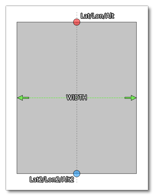
This element can be used to define a rectangular surface in a scene. It is generally used for terraforming an area and for changing the surface material within the rectangle. The rectangle is defined by supplying two sets of coordinates for latitude, longitude and altitude, which will set the positions for two sides of the rectangle, while the width value sets how wide the rectangular area will be between those points. The diagram below helps illustrate this:
This element can contain the <RunwayDeformation /> as well as the <Heightmap/> sub-elements, and takes the following attributes:
| Attribute | Description | Type | Required |
|---|---|---|---|
width |
The total width of the rectangular area, in meters. | Float | Yes |
falloff |
Defines the range of terrain affected by the flattening of the rectangular area, higher value meaning an increase range. | Float | Yes |
surface |
Material to apply to the rectangular surface. If not supplied, then the original terrain surface material will be used. |
String: "CONCRETE" |
No |
precision |
When set to "false", Default is "True" |
Bool | No |
lat |
Latitude of the first side of the rectangular area. | Float | Yes |
lon |
Longitude of the first side of the rectangular area. | Float | Yes |
alt |
Altitude of the first side of the rectangular area, in meters. Please note that the referential for this value is always ELLIPSOID. | Float | Yes |
lat2 |
Latitude of the second side of the rectangular area. | Float | Yes |
lon2 |
Longitude of the second side of the rectangular area. | Float | Yes |
alt2 |
Altitude of the second side of the rectangular area, in meters. Please note that the referential for this value is always ELLIPSOID. | Float | Yes |
priority |
This value is used to define the order in which the terraforming rectangles should be applied. | Integer | No |
<Heightmap/>
This sub-element can be added to a <Rectangle> to define a set of heightmap values to the area being terraformed. This element takes two attributes:
| Attribute | Description | Type | Required |
|---|---|---|---|
width |
The width of the data grid. | Integer | Yes |
data |
A list of altitude values, where each value is separated by a space, eg:
|
String | Yes |
The heightmap will be applied to the entire rectangle, and the attributes are basically defining a grid of values where:
number_of_data_values = width * length
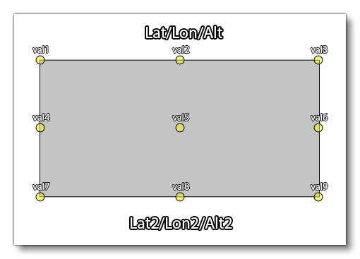
For example, say we want to apply a heightmap of 9 points to the defined rectangle. We'd use this element like this:
<Heightmap width="3" data="val1 val2 val3 val4 val5 val6 val7 val8 val9" />This would then be applied to the rectangle like this:
<ExclusionRectangle />
This element can be used to define a rectangular area which can be used to exclude specific elements. The elements to be excluded are supplied as attributes to the element and are listed in the table below.
IMPORTANT! This element will not exclude anything from the current package being edited. It is only valid for removing things from a previously loaded package, and is dependent on the package load order. So, packages loaded after the package with the <ExclusionRectangle> will be rendered as normal, and packages loaded before the package with the <ExclusionRectangle> will have elements excluded.
NOTE: Exclusion rectangles will only apply to SimObjects placed via the Scenery Editor. They will not apply to BGL traffic or SimObjects spawned using SimConnect.
This element has no children and is self closing, and it uses the attributes listed below:
| Attribute | Description | Type | Required |
|---|---|---|---|
latitudeMinimum |
The minimum latitude for one side of the rectangle. | Float | Yes |
latitudeMaximum |
The maximum latitude for one side of the rectangle. | Float | Yes |
longitudeMinimum |
The minimum longitude for one side of the rectangle. | Float | Yes |
longitudeMaximum |
The maximum longitude for one side of the rectangle. | Float | Yes |
excludeAllObjects |
Setting this will exclude all objects within the rectangular area (in which case none of the other attributes are necessary). | Bool | No |
excludeBeaconObjects |
Setting this will exclude any beacons within the rectangular area. | ||
excludeCarParking |
Setting this will exclude any car park objects within the rectangular area. | ||
excludeEffectObjects |
Setting this will exclude any legacy effect objects within the rectangular area. | ||
excludeExtrusionBridgeObjects |
Setting this will exclude any extruded bridge objects within the rectangular area. NOTE: Extruded bridges are deprecated in Microsoft Flight Simulator 2020, so including this attribute will make no difference to rendering. |
||
excludeGenericBuildingObjects |
Setting this will exclude any generic building objects within the rectangular area. NOTE: Generic buildings are deprecated in Microsoft Flight Simulator 2020, so including this attribute will make no difference to rendering. |
||
excludeLibraryObjects |
Setting this will exclude any library objects within the rectangular area. | ||
excludePolygons |
Setting this will exclude any polygons within the rectangular area. | ||
excludeProjectedMesh |
Setting this will exclude any projected meshes within the rectangular area. | ||
excludeRectangles |
Setting this will exclude any rectangles within the rectangular area. | ||
excludeSimObjects |
Setting this will exclude any SimObjects within the rectangular area. | ||
excludeTaxiwaySignObjects |
Setting this will exclude any taxiway signs within the rectangular area. | ||
excludeTriggerObjects |
Setting this will exclude any Triggers within the rectangular area. NOTE: Triggers are deprecated in Microsoft Flight Simulator 2020, so including this attribute will make no difference to rendering. |
||
excludeVisualObjects |
Setting this will exclude any Visual Effect objects within the rectangular area. | ||
excludeWindsockObjects |
Setting this will exclude any windsocks within the rectangular area. | ||
excludeWorldScripts |
Setting this will exclude any world script objects within the rectangular area. | ||
excludeAirports |
Setting this will exclude the airport that it has been placed over. This requires that the exclusion rectangle covers the center point of the airport, and will prevent all airport objects from spawning, including towers, runways, aprons, etc... Note that this will not change any ground textures, and so - if the airport being excluded exists in the real world - there may still be airport areas visible in the TIN. |
<LandmarkLocation />
This element has no children and is self closing. It is used to designate a particular location as a "landmark", which will then be shown to the user both in the world map and in the world itself when flying around. This element has the following attributes:
| Attribute | Description | Type | Required |
|---|---|---|---|
instanceId |
GUID used to identify this instance of the element. | String | Yes |
type |
The type of landmark object marker to use. One of the following:
|
String | |
name |
The name of the landmark. This string can be localised. | String | |
lat |
The latitude where the landmark appears. | Float | |
lon |
The longitude where the landmark appears. | Float | |
alt |
The altitude where the landmark appears. | Float | |
offset |
This is an offset for the height of the landmark marker. Normally this is simply left at 0, but if you have multiple landmarks in a similar area, you can use this offset value to ensure that all the markers are seen without any overlap. | Float |