PROJECTED MESH OBJECTS
NOTE: This object is not available when the Scenery Editor is in World Hub Mode.
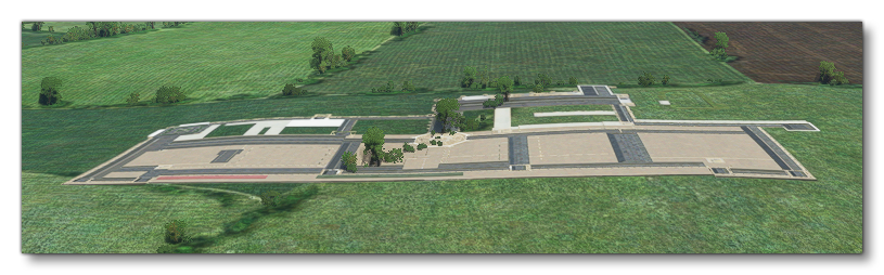
A projected mesh object is an object element that is used as part of an airport to add detail to terrain. A projected mesh takes a scenery object, but - instead of drawing it in 3D - the mesh will be projected on the ground and rendered in 2D.
If several meshes are drawn on top of each other, they must have different priorities. The lowest priority is rendered first and higher priorities are rendered over it. By default, they are drawn below every other object in the airport, although this behavior can be changed with the Draw Before option in the Properties.
NOTE: User created models with translation/rotation/scaling applied to them on export from the chosen 3D editor will not have these transforms applied when added into the game as a projected mesh. If you require these transforms, you need to either use the scenery editor Gizmo to do the transform - in which case the model should be exported without any transforms - or carefully make all the transformation to the model before exporting in the 3D editor.
When you select this object type you will be presented with a list of different scenery object elements listed in the Objects window:
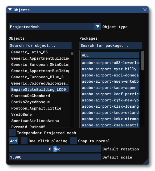 The exact number and kind of elements listed will depend on the version of Microsoft Flight Simulator 2020 that you are running as well as what packages you have installed and whether you have added any custom ModelLib packages. To place a Projected Mesh object element in the scene you can click the
 Add button, and then use the Translate Gizmo to position the object where you want, or you can enable One-Click Placing and simply click in the world to place it. You may also use the Rotation Gizmo to change the angle the element is shown at, as well as the Scale Gizmo to change its size.
By default, Projected Mesh objects require one or more Airport Objects to be present in the scene, and will be added to an airport group in The Scenery Editor. If no airport is present and you still require a Projected Mesh, then you should check the box labelled Independent Projected Mesh before adding it to the scene.
IMPORTANT! If a default airport Projected Mesh is placed too far away from the airport (ie: outside the airport Object Test Radius) then it will not be rendered.
Once you place a Projected Mesh in the scene, the Scenery Editor will show a Projected Mesh group with a single child that is the mesh that was just placed (if the projected mesh is independent then the group will be created in the scenery root, otherwise it will be created within the airport group). Both the group and the mesh object have properties that can be set, explained below. Note that after placing the object you may get a warning in the Scenery Editor contents list:
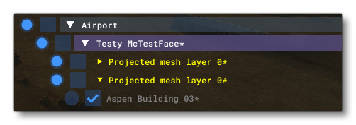 If you mouse over the element in the list you'll get a tooltip that shows exactly what the issue is:
 These warnings will not make the package invalid, but they are things you should be aware of as they may affect the way the object is finally rendered. To avoid these issues your custom meshes should be exported without translation, rotation or scale, and only materials that contain these texture combinations should be used:
- albedo
- albedo + metal roughness AO
- albedo + normal map
- albedo + normal map + metal roughness AO
NOTE: When they are present, metal and AO components are not used.
IMPORTANT! When being rendered, projected meshes are baked into the terrain textures. This helps reduce the polycount and permits the element to be terraformed. However, it also means that the texture quality won't be any greater than the resolution of the terrain textures themselves. In general, this resolution is around 4cm/pixel at the equator, with the best/highest resolution terrain textures reserved for higher LODs so we have a better quality for airports. For users, they will experience the best resolution possible setting the "Terrain level of detail" option to its maximum value.
Projected Mesh (Group) Properties
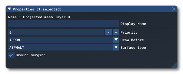
Projected Mesh groups have the following Properties which can be edited (regardless of whether they are within an airport or independent):
-
Name
This is the name of the projected mesh object element as defined from its file.
-
Display Name
This is the name of the projected mesh group as it will be displayed in the The Scenery Contents List. This can be edited and is helpful for identifying elements when you have a lot of items in the content list.
-
Priority
This option sets the render priority for the projected mesh object. The default render priority is 0, which for most cases is fine. However, if you have overlapping meshes and want one to render over another one, then you will need to change this value clicking the
+or-buttons to raise or lower the priority value. Higher priority values will render over lower priorities, for example, a mesh with priority 1 will render over one with priority 0, which in turn will render over one with priority -1. Note that the engine cannot guarantee the render order for meshes with the same priority, so if you need something to always render over or under something else, you need to set this value.
-
Draw Before
This option permits you to place meshes into the render hierarchy so that they are drawn under or over different elements. When you click this option, you will be shown a list of object elements which are shown in the order they are rendered. When you pick one, the projected mesh will be rendered over the previous object types, and under the subsequent types. For example, if you select MARKINGS, then the projected mesh will be rendered over Aprons, Taxiways and Runways, but under Markings, Runway Markings and Marking Text.
-
Surface Type
This option permits you to select from a list of default surface types that can be applied to the projected mesh. These surfaces will be merged with the mesh texture to add further visual variety and better integrate the mesh with the terrain and surrounding elements.
-
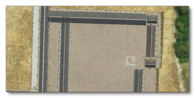
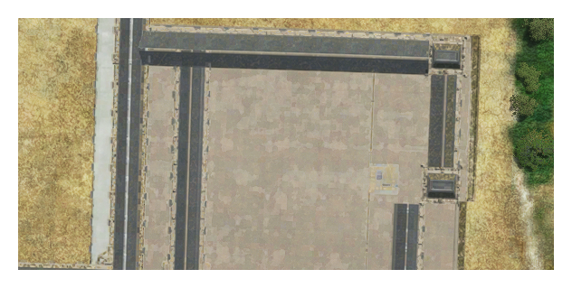
Ground Merging
When checked, this option will merge the terrain textures with the material textures that are used for the projected mesh. Mouse over the image below to see the difference:
Notes On Snow Coverage
It is worth noting that snow coverage for a projected mesh is dealt with automatically by the simulation and will depend on the following factors:
- colour: the darker areas of the combined ground / projected mesh will have less snow cover.
- material: the following materials will further reduce the snow cover if used on the projected mesh - asphalt, cement, paint.
- roads: if there is a road over the ground where the projected mesh has been added, then that too will have reduced snow cover.
Projected Mesh Properties
Projected mesh objects have the following Properties which can be edited:
Note that projected mesh objects will be shown automatically as invisible, locked, and unable to be edited in The Scenery Contents List:
This is because, while editing the scenery, the actual object is used to create the projected mesh, but this object is not required by the final package as the mesh will be baked into the glTF file. So, you edit the projected mesh group, not the object it contains that creates the mesh.
-
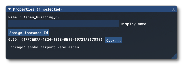
Name
This is the name of the projected mesh object element as defined from its file.
-
Display Name
This is the name of the projected mesh object element as it will be displayed in the The Scenery Contents List. This can be edited and is helpful for identifying elements when you have a lot of items in the content list.
-
Assign Instance ID
Clicking this button will create a GUID-formatted Instance ID unique to the instance of the projected mesh element placed within the simulation. This is distinct to the GUID value (explained below), as the GUID will be shared by all elements of the same object, while the instance ID will be unique to each instance of that object. This can be useful for many things like when creating mission scripts (for example).
-
GUID
This shows the unique GUID for the projected mesh element. This ID value is for the base object element itself, and will be shared with all instances of the element that are placed in the world. Use the
Assign Instance IDbutton if you require a unique GUID for a specific instance of the object element, and you click theCopybutton to get a copy of the GUID if required.
-
Package
This shows the name of the package that the currently selected projected mesh object element comes from.