VECTORPLACEMENT OBJECTS
NOTE: This object is not available when the Scenery Editor is in World Hub Mode.
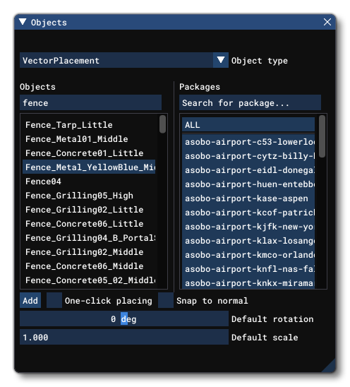
A VectorPlacement object is an object element that is used to place models into a scene such that they follow one or more vector lines across the landscape. This is especially useful for creating fences and other scenery elements that require repeating models. When you select this object type the Objects window will llook like this:
Note that with this kind of object, they can currently only be placed within a scene as part of an Airport Object hierarchy, and that you can only use static scenery models to place on the path as SimObjects cannot be used.
Adding Points
Adding a VectorPlacement object requires you to add at least two points into the world to define the vector that will be used for the model placement. This is achieved by simply selecting the object type then selecting the model that you want to use (this can be changed later if required) then click on the Add button. The cursor will then have a red point attached to it, and if you hold down Ctrl and use the Left Mouse Button you can start to place points on the world to outline the vector path. When you are happy with the vector you have delineated, you can press Enter to "fix" the path:

The VectorPlacement object will have a Gizmo in its center and this can be used to change the position/rotation/scale of the entire vector path. If you wish to remove the polygon object from the world, you can select it and then press the Delete key.
If you want to change the position of any of the points defining the vector after you have created it, you can click the Left Mouse Button on the point to set the gizmo to that point. This point can then be translated to a new position using the gizmo or by inputting new values in the gizmo window. You can also use Ctrl and click to select multiple points and move them all at once, and if you make a mistake you can use Ctrl + "Z" to undo the last action.
RMB Options
VectorPlacement objects also have specific commands available from the Right Mouse Button menu:
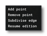 The first options are general for all objects and are explained in the section on The Scenery Contents List, so we'll concentrate here on the options unique to this object:
- Add Point: When you right click on a vector of the path and select this option, a new point will be added to the vector at the position that was clicked.
- Remove Point: Right clicking and selecting this option on any point of the vector path will remove that point. You can also click a point and hit
Deleteon the keyboard to remove a point. - Subdivise Edge: When you right click on a vector and select this option, a new point will be added to the center point of the vector.
- Resume Edition: Selecting this option will put you back into the edition mode, the same as when you first added the vector placement object to the scene. There will be a red point and you can add points to the vector path using
Ctrl+ Left Mouse Button, and then finalise usingEnter.
Properties
The Properties window for a Vector Placement object looks like this:

The options presented to you here are:
-
Display Name
This is the name of the element as it will be displayed in the The Scenery Contents List. This can be edited and is helpful for identifying elements when you have a lot of items in the content list.
-
Model GUID
This shows the unique GUID of the model that has been selected for the vector placement.
-
This button will open the model selector window and permits you to change the model that is being used for placement along the vector path.Replace Model
-
Snap To Vertices
Selecting this button will stop the chosen model from being placed along the lengths of the vectors, and instead only be placed on the single vertices (points) that make up the vector path.
-
Spacing Between Models
This sets the spacing (in meters) between the models as they are placed along the vector path. This is set to 50m by default, and can be altered to bring the object models closer together to keep continuity between them, ideal for placing something like a fence. To edit the value you can either click on it and drag left or right, or double click the value then enter a number manually using the keyboard.

-
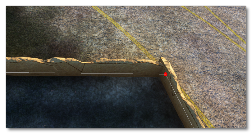
Avoid Discontinuity
This option can be ticked to have the scenery editor try and ensure that the models used match up correctly at the corners of the vector path. The image below shows a VectorPlacement object with this option disabled, and if you mouse over the image you can see what difference it makes when enabled: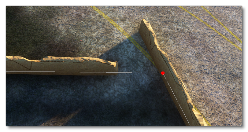
-
Rotation Type
This option permits you to change the way the model rotation will be handled by the simulation. Selecting this presents the following options:
- Follow Edge: The models will be orientated relative to the direction of the vector path it follows
- Same: All the models will be orientated in the same, single direction, which can be edited using the Model Headings parameter (below).
- Random: Each model will be given it's own random orientation regardless of the position it occupies along the vector path.
-
Model Headings
This option can be used to modify the orientation (heading) of the model. This will be a relative orientation if the Rotation Type is set to Follow Edge or Random, and an absolute orientation if the setting is Same. To edit the value you can either click on it and drag left or right, or double click the value then enter a number manually using the keyboard.
-
Model Scale
This value is used to scale the model up or down. The base value is 1, and a value less than one will scale it down and a value greater than 1 will scale it up. This will also be cumulative with the scale applied if the Random Variation option is greater than 0.
-
Model Scale Random Variation
This option will add a random variation in scale to each model placed along the vector path. The default value is 0, which is no random variation, and any value greater than 0 will be used to apply a random variation in size to each model using the given value as a magnitude for the variation. This variation will be cumulative with the Model Scale setting.