AIRPORT OBJECTS
An Airport object is an object element used to add an airport area to the world. Adding this object will permit you to define certain meta-data for the Airport and then add airport-specific object elements from the Scenery Editor. These object elements are:
- Runway
- Helipad
- CarParking Objects
- TaxiwayPoint
- TaxiwayParking
- TaxiwayPath
- TaxiwaySign
- Apron
- Polygon Objects
- PaintedLine
- PaintedHatchedArea
- LightRow
- LightSupport
- Jetway (Not available for World Hub Airports)
- ControlTower Objects
- ProjectedMesh (Not available for World Hub Airports)
- VectorPlacement (Not available for World Hub Airports)
- Windsock Objects
When you select this object type the Objects window will not show any different object elements as there is only one type of airport and it's meta-data is defined through the Properties:
When you click the Add button, the Airport object will be added to the scene and can be positioned using the Gizmo. The position of this airport object will be used to define the airport reference point which is used for placing in-sim markers but otherwise has little bearing on the contents of the airport.
Note that when you add an Airport object to scene for the first time, it will be created in The Scenery Contents List of the Scenery Editor as a unique group rather than as a single object listing. This is because airports, while themselves an object, are also a type of "container" for other object types that can only be placed within an airport:

Any further airports you add to the package will be listed as an individual named group, and each named airport group will contain all the sub-groups and object elements that are created for it. For more information see the section on Scenery Groups.
Properties
The Properties window for an Airport looks like this:

-
Name
This is the name of the element as defined from its type. The name will be appended with additional information in brackets depending on the rest of the options in the Properties window (for example, the ICAO code or the Airport Name).
-
Display Name
This is the name of the element as it will be displayed in the The Scenery Contents List. This can be edited and is helpful for identifying elements when you have a lot of items in the content list.
-
ICAO
This is the ICAO code for the Airport being defined. This value is obligatory and you will get an error in the Scenery Editor if it's not supplied. Note that after entering the ICAO into the input field, you need to press the
Enterkey to confirm it.
-
Region Name
This is the name of the region the airport is in. Generally the region would be one of the following:
-
Japan
-
Asia (China, India, Sri Lanka, Philippines, Taiwan, etc...)
-
North America (Canada, USA)
-
Latin America (Argentina, Cuba, Venezuela, Brazil, etc...)
-
Middle East (UAE, Israel, Saudi Arabia, Iran, etc...)
-
Europe (France, Spain, Germany, United Kingdom, etc...)
-
Africa (Tunisia, Chad, Kenya, Madagascar, etc...)
-
-
Country Name
This is the name of the country the airport is in.
-
State Name
This is the name of the state the airport is in.
-
City Name
This is the name of the city that the airport is either in or nearest to.
-
Airport Name
This is the name of the airport itself and will be displayed to the user. This value is obligatory and you will get an error in the Scenery Editor if it is not supplied.
-
Magvar
This is the magnetic variation for the airport position. This is the angle difference between the magnetic north and true north. A negative value here means it's to the east and positive value is to the west, and the value is measured in degrees between -360.0° and 360.0°.
-
Object Test Radius
This is the radius around the airport reference point in which you are permitted to place any of the listed airport objects. In the world, this can be seen rendered as a dark blue circle.
-
Apply Flatten
Checking this option will auto-generate terraforming rectangles within the bounds of the airport test radius to flatten the terrain. These rectangles are internally defined and not rendered in the world as objects, although their effects will be visible on the terrain.
-
Star Airport
Checking this will make the airport a "star" airport on the world map, highlighting it to users.
-
TIN Colour Correction
This option is enabled by default on all new airports and applies colour correction to certain airport features - mainly runways and aprons - to eliminate unnatural TIN colours bleeding into them. Mouse over the image below to see an example of the difference this option can make (note that the difference will depend on the location):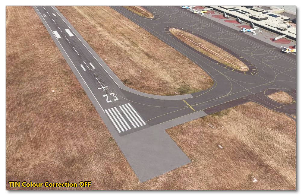

-
Closed Airport
When checked, this will stop the airport from being accessible or interactive in any interface such as the world map, the instruments or the ATC system. Essential meaning the airport is only going to be rendered and nothing else.
-
Generate Taxiway Signs
Clicking the Generate Taxiway Signs button will add auto-generated Taxiway Sign Objects to the airport based on the TaxiwayPath Objects that have been added. This button requires at least one taxiway path to exist in the airport.
Ground Merging
When you expand the Ground Merging section, initially you'll be presented with a single button: Setup Transfer Parameters. Clicking this will expand the Properties window to show the following:
 Basically, these sliders define how much aerial map detail will remain visible by changing the transparency of the lighter (transfer bright) and darker (transfer dark) areas of the element individually.
NOTE: This option is only valid for Apron Objects in the airport.
You can disable this option by clicking the Remove Parameters option which will remove the bright/dark parameters from all applicable ground elements.
Delete Command
When you expand the Delete Command section of the Airport properties you'll see the following list of options for deleting object elements:
 These various options can be used to remove selected object elements from the airport being rendered. Note that this does not include anything actually in the current airport! The options provided here are meant to delete things from a previously loaded package, and is dependent on the package load order. So, packages loaded after the package with this airport will be rendered as normal, and packages loaded before the package with this airport will have elements removed. Essentially this is a mechanism designed for overwriting an existing airport from another package.
Frequencies (Not available for World Hub Airports)
 The Frequencies section permits you to define the exact frequencies of certain navigation and communication systems. To add a new frequency, click on the Add Frequency button, then fill in the following details:
-
Frequency
The frequency (in MHz) that for the system you are defining
-
Type
The type of system being defined, which can be any of the following:- APPROACH
- ASOS
- ATIS
- AWOS
- CENTER
- CLEARANCE
- CLEARANCE_PRE_TAXI
- CTAF
- DEPARTURE
- FSS
- GROUND
- MULTICOM
- REMOTE_CLEARANCE_DELIVERY
- TOWER
- UNICOM
-
Name
The "common name" that you wish to give the frequency.
Light Presets (Not available for World Hub Airports)
Light presets are a work-in-progress feature that aim to make it easier and quicker to add lighting to your airport. The basic principle is that you can create one or more light presets for an airport, and then apply these presets to any of the possible lighting object elements that you add, permitting you to create sequenced strobe lights or pulsing directional lights, etc...
IMPORTANT! As this is WIP, please use with caution. Also note that currently this feature can only be applied to LightRow object elements.
When you expand this option you'll be presented with a single button: Add Light. Clicking this will add a new light preset and expand options for the light that you are adding:
 Here you can first Name the preset. This name will then be shown in those other object elements that permit it (currently only LightRow objects) so that you can select this preset for the lighting to use. Next you can set the Incremental Phase for the light. This one is only applicable if you have set the Phase property for the light type within the preset (explained below). Essentially, this is a value that will be added to the light phase in an incremental fashion so that all lights using this preset phase in sequence rather than at the same time. Finally, you can select a mesh or the light by clicking the
 Select mesh button.
Once you have set up the basic preset values, you can go ahead and add lights to the preset. This is done by clicking the Add Light button, which will further expand the properties with options for the light (note you can add further lights to the preset and they will each have their own options, and you can remove lights from the preset by clicking the X button):

- Type: This is the type of light that is being defined. Can be one of the following:
| Light | Description | Illustration |
|---|---|---|
| Omni-Directional | Light will be visible form any direction. |  |
| Uni-Directional | Light will be visible from the half-space defined by the position and the direction. Essentially a 3D "cone" of light with falloff from all "front" angles, but not visible from the "back". |  |
| Angled Directional | This is similar to the uni-directional light, only the second direction value is used to define the normal for a cutoff plane where the light is not visible if viewed from below that plane (generally only useful for VASI lights). |  |
| Double Angled Directional | This uses two directional normals to define two cutoff planes. Light will only be visible from the sides or when viewed within the angles of the planes (generally only useful for VASI lights). |  |
| Fresnel |
Similar to the Double Angled Directional light, this light uses two normals to create cutoff planes for the light, however this light also has a position offset that moves it to be within the planes themselves. NOTE: This light currently does not function correctly and there is no way to define the positional offset. Future updates will fix this. |
 |
- Fade: Sets the type of fade to be applied to the light when it has Duration/Period/Phase settings. The options available are:
- No Fade - The light will simply switch between on/off
- Fade In - The light will fade on, then switch off
- Fade Out - The light will switch on then fade to off
- Fade In / Out - The light will fade between on and off
- Radius: The radius of the light, in meters. This is essentially the distance of the "glow" around the light.
- Intensity: The intensity of the light when fully on. Higher values will mean a more intense light which will be visible at a greater distance.
- Duration: The duration of the light "ON" phase
- Period: The combined total period of the light being on and the light being off (including fades in/out). For example, setting the duration to 10 and the period to 20 would have an "on" of 10 and an "off" of 10 (so the total is the period value of 20).
- Phase: An offset value for the light period so you can create sequences of flashing lights that flash on/off at different times but with the same period. Note that this will be combined with the general preset Incremental Phase value (if anything other than 0), so you can create complex effects of "marching" lights.
- Colour: The color of the light. You can input individual RGB component values (from 0 to 255 for each component), or you can click on the color box to open the color picker where you can define the color visually or using HSV or hex values.

- Relative Position: The input fields here permit you to offset the light from the position it was placed in the world along the Y/Z/X axis, where the X axis will follow the light row that the preset is applied to. Values are in meters.
- Direction: The direction of the light set using Y/Z/X axis values, in meters, and the values used here will be added to the local frame of reference for the components that use the preset. This parameter is used by all lights except the omni-directional type. Note that for Double Angle Directional and Fresnel lights, this value is for defining a normal from which a cutoff plane will be created for the light. Note that there is an option in The Rendering Menu to help make the positioning of this vector easier: Show Parking Spaces
- Direction 2: The second direction of the light set using Z/X/Y axis values, in meters, and the values used here will be added to the local frame of reference for the components that use the preset. This is only used by the Angled Directional, Double Angled Directional, and Fresnel lights to set a normal for the cutoff plane used by those lights. Note that there is an option in The Rendering Menu to help make the positioning of this vector easier: Show Parking Spaces