IMPLEMENTING LIGHTS
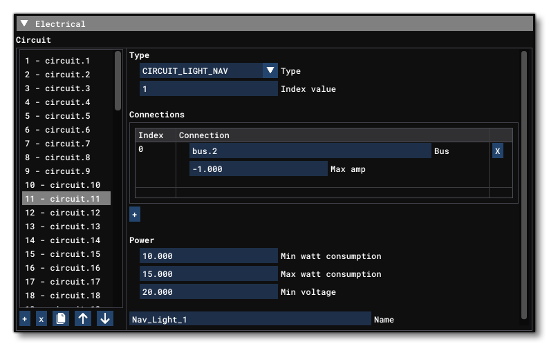
To set up the aircraft lights, you will first have to create a circuit for the type of light in the Aircraft editor Systems tab, under the Electrical section:

Usually you would have named the circuit according to the light it is to be controlling, and you would also include - along with the name - an index that matches with the light index (if you need multiple lights of that type). This is written to the system.cfg (as outlined here: Circuits):
[ELECTRICAL]
...
circuit.11 = Type:CIRCUIT_LIGHT_NAV:1 #Connections:bus.2 #Power:10, 15, 20.0 #Name:Nav_Light_1 ; nav 1 light 15W
circuit.12 = Type:CIRCUIT_LIGHT_NAV:2 #Connections:bus.2 #Power:10, 15, 20.0 #Name:Nav_Light_2 ; nav 2 light 15W
circuit.13 = Type:CIRCUIT_LIGHT_NAV:3 #Connections:bus.2 #Power:10, 15, 20.0 #Name:Nav_Light_3 ; nav 3 light 15W
circuit.14 = Type:CIRCUIT_LIGHT_NAV:4 #Connections:bus.2 #Power:10, 15, 20.0 #Name:Nav_Light_3 ; nav 4 light 15W
circuit.15 = Type:CIRCUIT_LIGHT_BEACON:1 #Connections:bus.2 #Power:6, 8, 20.0 #Name:Beacon_Light ; Beacon light 28V @ 0.26A
circuit.16 = Type:CIRCUIT_LIGHT_BEACON:2 #Connections:bus.2 #Power:6, 8, 20.0 #Name:Beacon_Light ; Beacon light 28V @ 0.26A
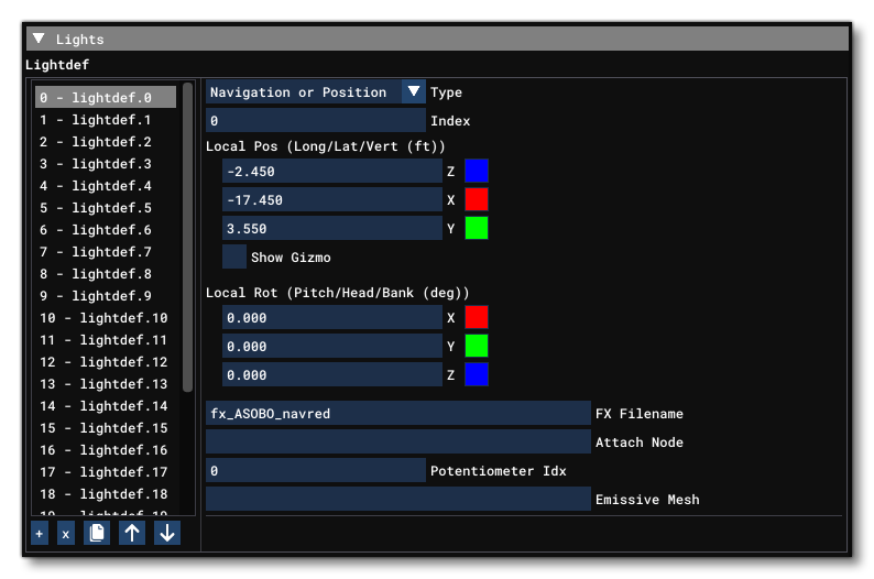
Once you have set up the light circuits, you then need to add in the actual light definitions. This is also done through the Aircraft Editor, from the Systems tab:

Generally the artists would set up the lights when implementing them art side, but the parameters will need to be modified later such that the Index and the Potentiometer (and the light type, if incorrect) can be adjusted to behave properly. When saved from the aircraft editor, the system.cfg file will look something like this:
[LIGHTS]
lightdef.0 = Type:1 #Index:1#LocalPosition:-11.5,0,11   #LocalRotation:0,0,0   #EffectFile:LIGHT_ASOBO_BeaconTop       #Node:                                #PotentiometerIndex:1 #EmMesh:LIGHT_ASOBO_BeaconTop
lightdef.1 = Type:1 #Index:2#LocalPosition:-3.4,0,-3.1  #LocalRotation:0,0,0   #EffectFile:LIGHT_ASOBO_BeaconBellyOmni #Node:                                #PotentiometerIndex:1 #EmMesh:LIGHT_ASOBO_BeaconBelly
lightdef.2 = Type:3 #Index:1#LocalPosition:-23,-55,5.6  #LocalRotation:0,0,0   #EffectFile:LIGHT_ASOBO_NavigationRed   #Node:LIGHT_ASOBO_NavigationRed       #PotentiometerIndex:1 #EmMesh:LIGHT_ASOBO_NavigationRed
lightdef.3 = Type:3 #Index:2#LocalPosition:-23,55,5.6   #LocalRotation:0,0,0   #EffectFile:LIGHT_ASOBO_NavigationGreen #Node:LIGHT_ASOBO_NavigationGreen     #PotentiometerIndex:1 #EmMesh:LIGHT_ASOBO_NavigationGreen
lightdef.4 = Type:3 #Index:3#LocalPosition:-79,0.2,7.8  #LocalRotation:0,0,180 #EffectFile:LIGHT_ASOBO_NavigationWhite #Node:LIGHT_ASOBO_NavigationTailRight #PotentiometerIndex:1 #EmMesh:LIGHT_ASOBO_NavigationTailRight
lightdef.5 = Type:3 #Index:4#LocalPosition:-79,-0.2,7.8 #LocalRotation:0,0,180 #EffectFile:LIGHT_ASOBO_NavigationWhite #Node:LIGHT_ASOBO_NavigationTailLeft  #PotentiometerIndex:1 #EmMesh:LIGHT_ASOBO_NavigationTailLeft
Finally, in the aircraft XML file you can use an existing model behaviour template (usually one with the format ASOBO_LIGHTING_<switch/push>_Light_<light type>_Template, which you can find here: Lighting.xml), or you can make your own template for the interaction.
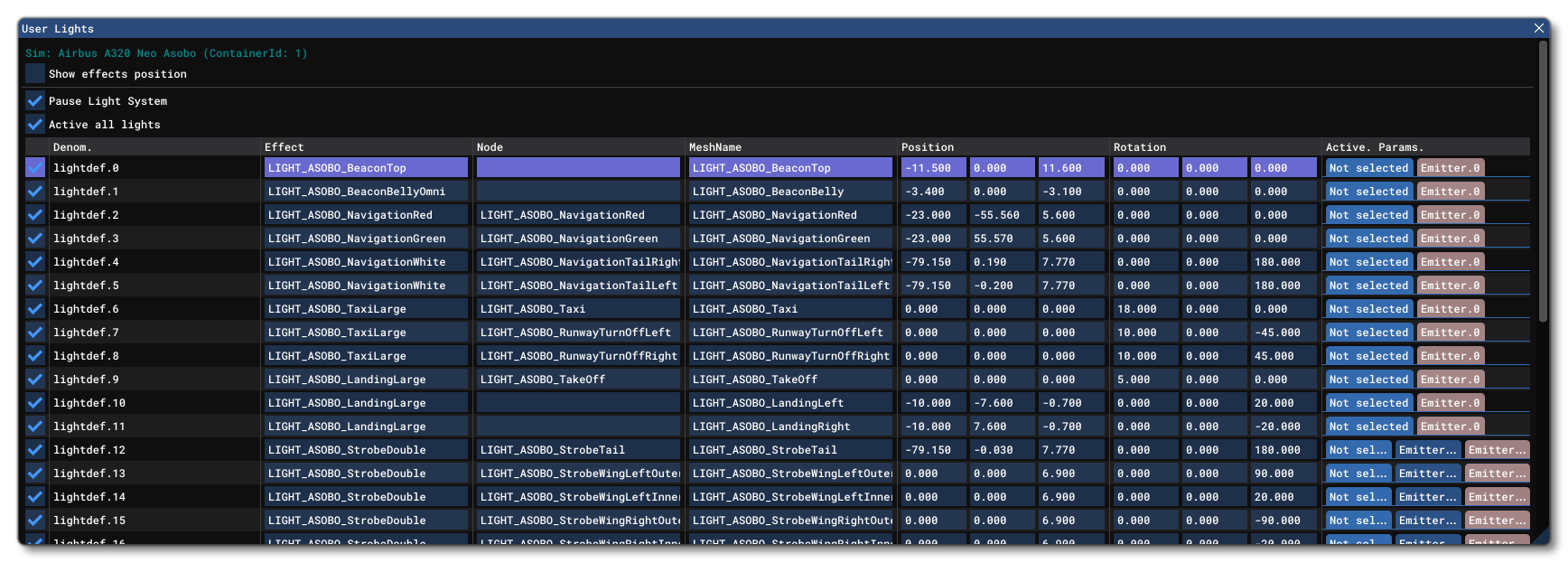
Once you have your model behaviors set up, check you are correctly triggering the electrical system and that the indexed SimVar takes the correct value, or that you are using the right potentiometer index. If the light still doesn't work - ie: nothing is showing - then this is probably a problem on the art side of things. However, you can check by using the User Lights debug window and toggling the effect manually from there:

If the light still doesn't work when using this debug window, there is a high chance something is wrong with the light itself (effect mesh, orientation, node attached etc.).
Note For GlassCockpit Emissive Elements
It's worth taking a moment to note how you use emissive textures within the glasscockpit display. This is done through the model behavior XML, using a template that can affect a material's emissive, such as ASOBO_GT_Component_Emissive_Gauge.
The easiest way to handle a screens emissive elements is to create a LocalVar that contains a percentage of brightness between 0 and 1. That percentage can then be connected to a knob which will be used to control it. The value can also be multiplied using the SimVar GLASSCOCKPIT AUTOMATIC BRIGHTNESS, which has a factor value that changes depending on the time of day, for example:
<Template Name="MyScreenTemplate">
    <DefaultTemplateParameters>
        <BRIGHTNESS_VARIABLE_TYPE>L</BRIGHTNESS_VARIABLE_TYPE>
        <BRIGHTNESS_VARIABLE_NAME>XMLVAR_#PREFIX#_#ID#_Brightness</BRIGHTNESS_VARIABLE_NAME>
    </DefaultTemplateParameters>
    <UseTemplate Name="ASOBO_GT_Component_Emissive_Gauge">
        <NODE_ID>#NODE_ID_SCREEN#</NODE_ID>
        <EMISSIVE_CODE>(#BRIGHTNESS_VARIABLE_TYPE#:#BRIGHTNESS_VARIABLE_NAME#) (A:GLASSCOCKPIT AUTOMATIC BRIGHTNESS, Percent over 100) *</EMISSIVE_CODE>
    </UseTemplate>
</Template>