AIRFRAME COLLISION MESHES
When making an aircraft there are a number of different collision meshes that will need to be created. Some of these are related to how the camera functions, others are for pre-flight activities and others are simply to register collisions with the terrain or other SimObjects. Most of these are explained in the sections below, however the following links pertain to certain collision meshes that are specific to a particular part of the airframe:
Drone Collision Mesh
The drone collision mesh is a rough collision mesh of the cockpit which prevents the cockpit free camera from moving outside, and - in drone (showcase) mode - it forces the display of the LOD0 of the cockpit as soon as the drone penetrates the mesh. It is also used as a fallback collision mesh for panel interactions in the case where the PANEL_COLLISION mesh is not found in the glTF.
IMPORTANT! This mesh should be exported as part of the airframe glTF, for the exterior LOD that will be visible in interior view (usually LOD0), and the normals/polygons of this mesh must be oriented toward the inside.
Note that - because of its inaccuracy - there may be places in the cockpit where some depth issues appear. This is to be expected and is not considered an issue.
In general you would make this mesh in the cockpit scene (using only a few polygons, with a closed geometry, and interior-facing normals), then import it into the airframe scene for use.

When creating this mesh, "DRONE_COLLISION_IN" must be the name of the root node of the collision mesh in the airframe part glTF. Note that if there are multiple seats in the cockpit cabin then you should also block out the seats as part of the collision mesh geometry to prevent the camera from clipping through them.
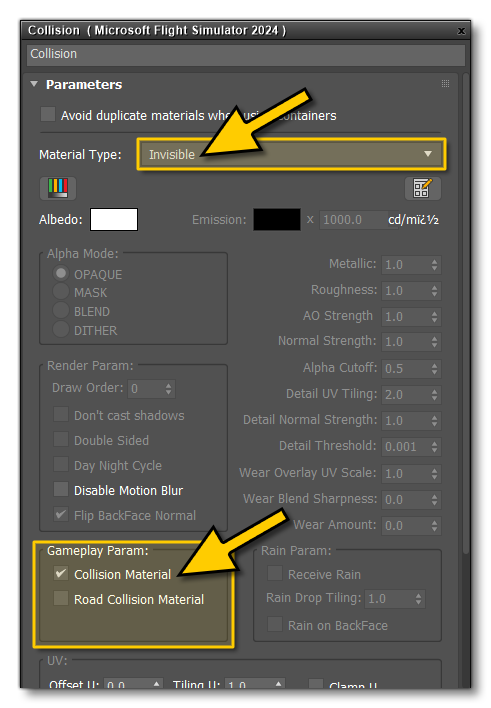
The material used for the collision mesh should be of the Invisible material type and the Collision Material flag must be checked:

NOTE: This material can be part of a multi-material and can also be used for other collision meshes. You do not need a unique material per-collision mesh.
In the simulation, the mesh is activated by retrieving the node that contains the mesh, and this node is found thanks to its name. Below you can see an example of the DRONE_COLLISION_IN mesh as seen from the interior of the Airbus A320 Neo:

Envelope Collision Mesh
The envelope mesh is one which loosely follows the aircraft mesh and will be used to detect any collisions between the aircraft and other physical objects in the simulation. The creation of this mesh starts with creating a single simple mesh around all the parts of the aircraft. The image below is the total collision mesh used by the Xcub aircraft:

The material used for the collision mesh should be of the Invisible material type and the Collision Material flag must be checked:

NOTE: This material can be part of a multi-material and can also be used for other collision meshes. You do not need a unique material per-collision mesh.
Once you have the total mesh, it should be generated for all LODs to prevent any specific LOD from not registering collisions, since different aircraft parts can be on different LODs when a collision occurs. The model can then be separated into the different parts that the aircraft will be split into to make it compatible with the modular aircraft system (as explained here: Aircraft Part Distribution). The aircraft shown in the image above has the following parts breakdown for the collision mesh:

We recommend that you put the meshes into layers based on part groupings for export, for example:
