-
AIRCRAFT MODELING GENERAL PRINCIPLES
This section lists some of the general modelling principles that you should follow when creating aircraft models for Microsoft Flight Simulator 2024. You can also find a list of more generic principles for all types of modeling as well as the glTF format on the following page:
Artistic Budget
Before getting started, it's good to be aware of the limitations of the simulation and the recommended polygon, vertex, material, and texture counts for the aircraft that you are making. Aircraft that go over the recommended limits will automatically have their visual fidelity lowered: if the LOD vertex count is too high for the current size on screen then the LOD is ignored and the next one is considered, and this check will continue down the LODs until a LOD with a vertex count under the hard limit for the size on screen is found. So we strongly recommend that you pay attention to these values when creating your models.
IMPORTANT! Previous versions of the simulation had different maximum counts based on the size of the aircraft. This is no longer the case and in Microsoft Flight Simulator 2024 there is simply a high cap for the whole aircraft that should never be reached. The mesh must remain as optimized as possible, but more details are allowed everywhere.
The table below is a general guide as to what kind of artistic budget you have for a single plane asset but note that these are maximum upper limits and you should always strive to be well below these values:
| LOD | Size On Screen | Triangle Count | Materials | Textures | Vertices (Hard Limit) |
LOD Reduction |
|---|---|---|---|---|---|---|
| x0 | >= 100% | 1,500,000 | 65 | 600 | 250,000 (scales up if the minSize is > 100%) |
LOD0 → LOD1: ~50% |
| x1 | 75% | 700,000 | 60 | 550 | 140,000 | LOD1 → LOD2: ~50% |
| x2 | 55% | 350,000 | 40 | 350 | 75,000 | LOD2 → LOD3: ~70% |
| x3 | 35% | 100,000 | 20 | 150 | 30,000 | LOD3 → LOD4: ~50% |
| x4 | 8% | 50,000 | 20 | 150 | 1500 | LOD4 → LOD5: ~80% |
| x5 | 5% | 10,000 | 6 | 50 | 300 | LOD5 → LOD6: ~1% |
| x6 | 1% | 100 | 1 | 0 - 1 | 150 | - |
IMPORTANT! The upper limit of 1.500.000 triangles includes everything - the cockpit, cabin, attachments, livery, dirt overlays, frost overlays, ground service equipment, preflight attachments, etc...
The table above is an ideal reference for starting the creation of an aircraft, but it doesn't tell the whole story since aircraft in Microsoft Flight Simulator 2024 are now modular in nature. This means that - depending on the distance to the camera - different parts of the aircraft will be on different LODs. For example, viewing the aircraft from the side could mean that the near-wing tip is LOD0, the wing body and fuselage are on LOD1, and the far wing body and tip, as well as the tail, are on LOD2. Consider the DA62: The model in 3DS Max has a polygon count of 1,133,429, but when viewed in the simulation from the tip of the wing the polygon count is 704,450.
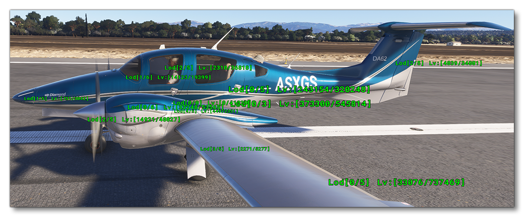
The image above shows how the DA62 is using different LODs for different parts. In previous versions of the simulation with the camera this close the full LOD0 would be loaded, however with the modular approach, only the LODs required for the appropriate minSize are loaded. This means that you can have a much higher fidelity aircraft in the modeling software, as long as the maximum polygon, vertex, material, and texture counts don't exceed the given maximums when loaded into the simulation.
For more in-depth information on LODs, minSize, bounding spheres, etc... please see here:
Aircraft Part Distribution
Since aircraft in Microsoft Flight Simulator 2024 are modular in nature, it is worth considering the parts breakdown before starting the actual modeling. The general idea here is to have a root node and then attach the central model to that, which will then be surrounded by peripheral models, for example:
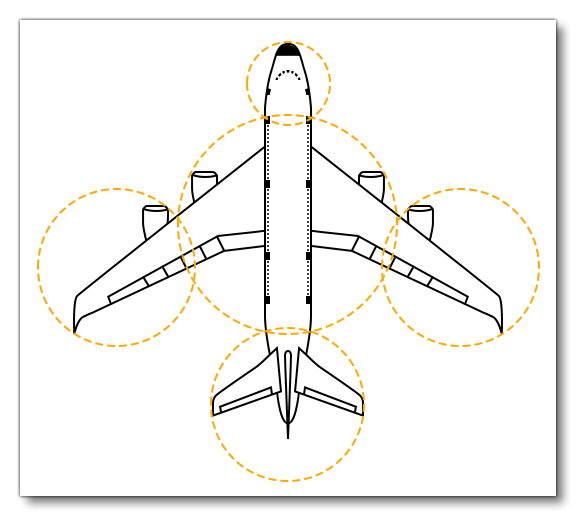
This is a typical minimal parts breakdown, which is essentially:
- Nose
- Tail
- Main Airframe
- Wing Tip Left
- Wing Tip Right
This can then be further broken down to separate out any remaining areas that have a high density of polygons, for example:
- Landing Gear
- Wheels Wells
- Engines
- Any detailed technical panels (fueling system, electrical system, etc…)
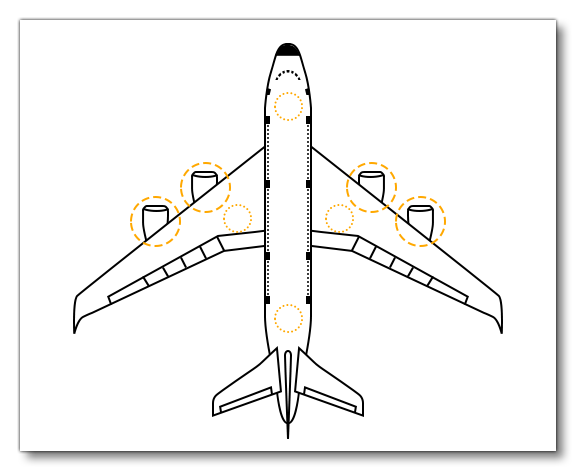
By breaking down the aircraft into parts, the parts that are viewed as "far" from the camera will be displayed at lower LOD levels than those parts that are "closer" to the camera. This means that you can have higher visible details, yet more performant aircraft. However there are a couple of things to note here:
- Avoid splitting the aircraft into parts that occupy approximately the same place and have a similar bounding sphere size and position. This will not be useful when it comes to performance since the two parts will almost always be on the same LOD level.
- It may be tempting to split a heavy part (like a fuselage) into two or more models to benefit farther LOD transitions, but this is not considered a "safe" practice. Keep in mind that if the LOD limits discard one of the LODs because the polygon density is too high relative to its size on screen, then you may get very obvious mismatches in the model geometry and textures
- After the first pass on the aircraft model, it is important to check the bounding sphere size and position is what you would expect for each of the parts of the model. This can be seen using the Display Bounding Spheres option in the Debug LODs window. If the sphere ios not shown where you expect then the model potentially has isolated vertices or the object has not been exported at 0, 0, 0.
Normal Maps
The Microsoft Flight Simulator 2024 engine prefers mesh over texture resolution, therefore more geometry is spent on defining detail that would otherwise be defined with normal maps. However, you should still use normal maps for rivets, micro-bump surface detail, and organic or flexible surfaces. You can also use normal maps for very small detailed areas that would otherwise use up a lot of triangles such as areas that involve a lot of cabling, chassis pressings, screws etc...
Weld Surfaces
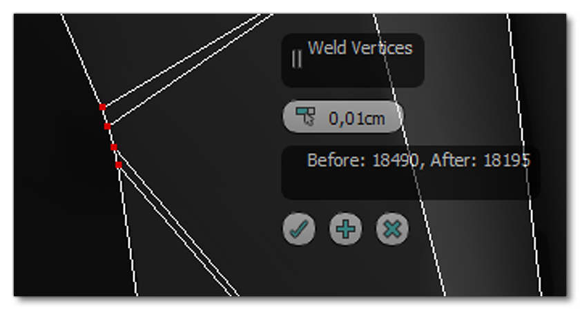
It is very important to ensure that you don't have any isolated or duplicated vertices within your models. This can be resolved by applying Weld Surfaces (3DS Max) or the Weld Modifier (Blender) to every object, for example:
Safety Cuts
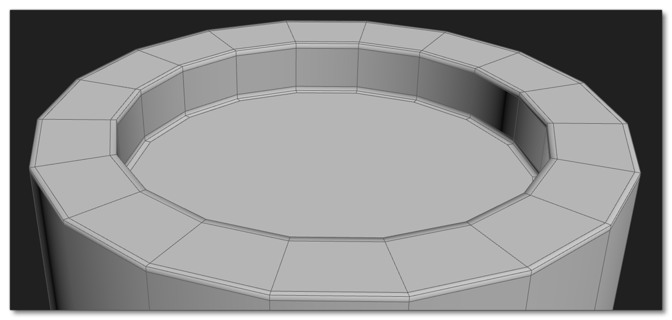
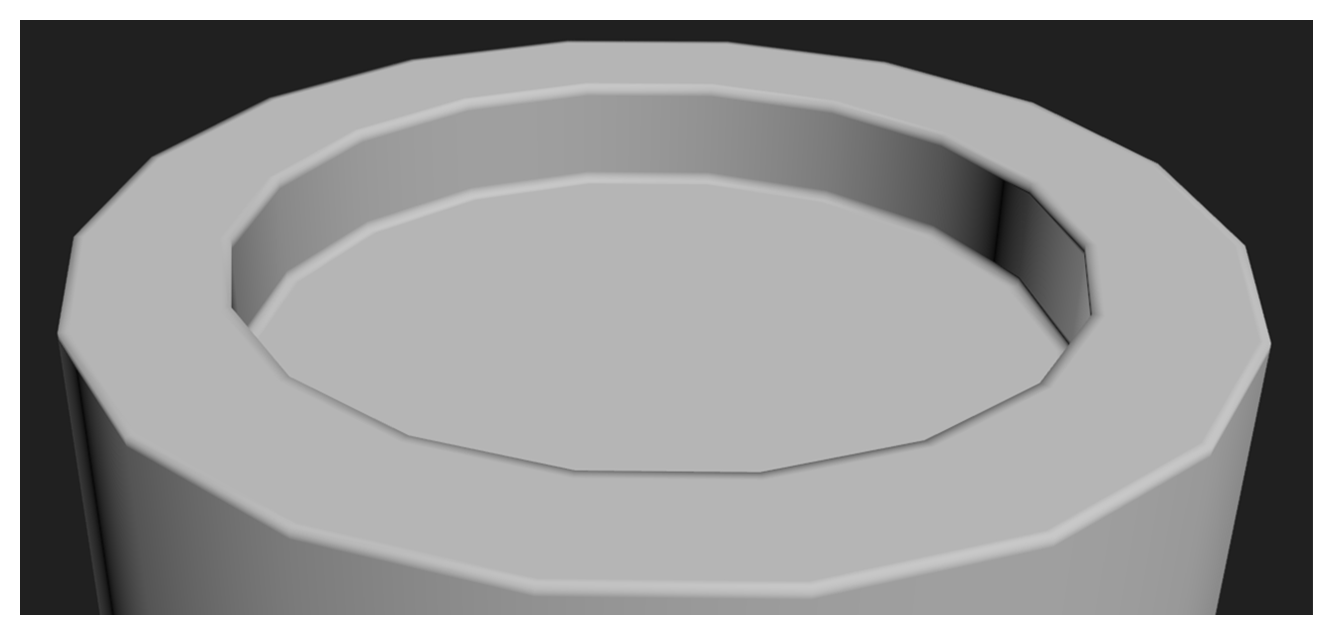
When creating your aircraft meshes they should be as clean and even as possible, and they should make good use of safety cuts. The image below illustrates this, and if you mouse over it you can see how the example mesh looks using a single Smoothing Group:
Turning Edges
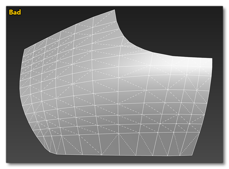
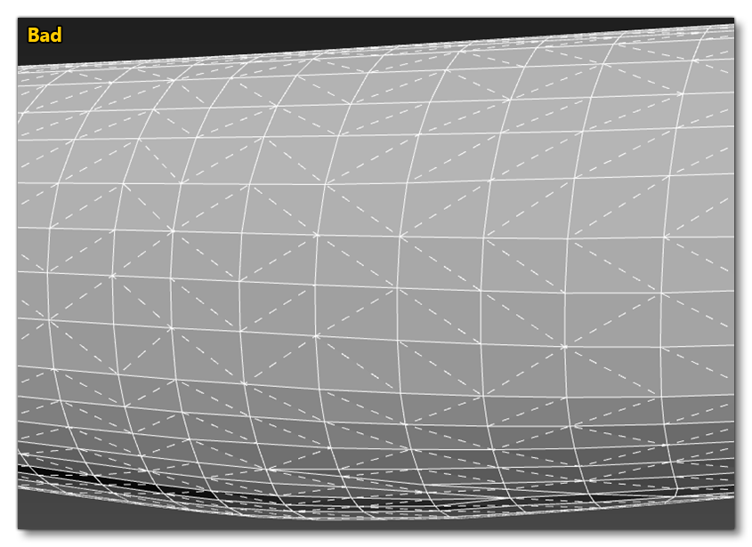
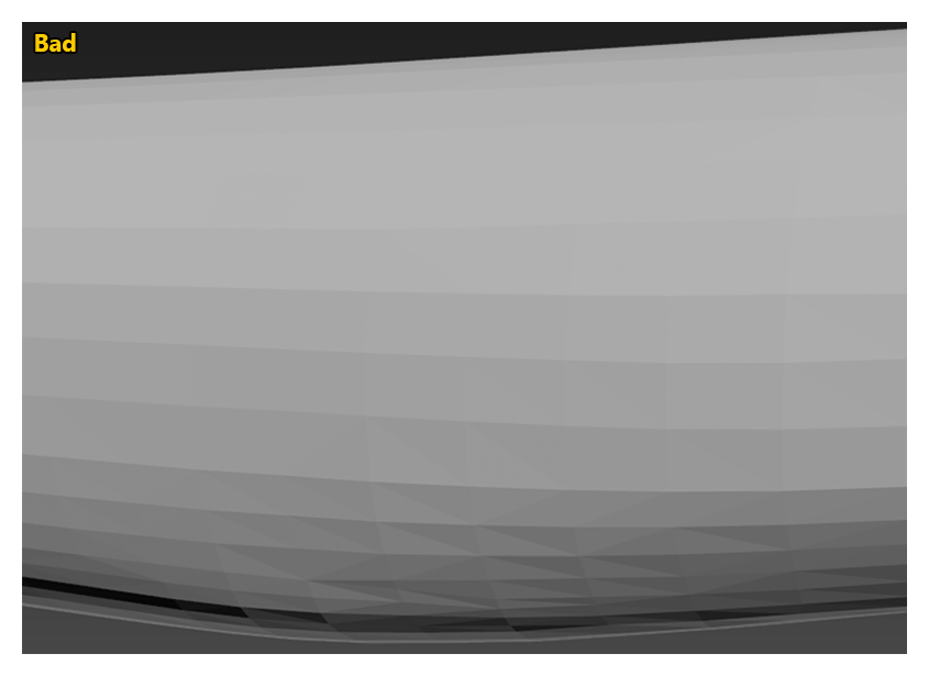
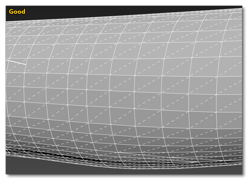
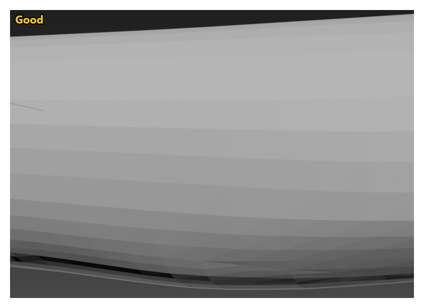
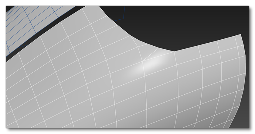
An important part of creating the aircraft model is ensuring that all the invisible polygon edges are turned so that the specular highlights and reflections have minimal distortions and flow correctly along the mesh. The image below shows a model with bad edges, and if you mouse over the image, you can see how it would look when corrected:
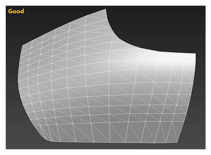
On large areas of mesh it is good practice to set the render mode to facetted in order to see the mesh with no smoothing. When in this view, you should be able to see nice clean gradients across your mesh, and this view will greatly will help when it comes to turning edges correctly.
To get a better idea if the difference this makes, here are two final images taken of the fuselage of a 747. The top image is without correcting the invisible edges and the bottom image is with corrected edges (if you mouse over the images you can see the mesh without the wireframe to see how the hidden edges affect lighting and gradients):
Quads And TurboSmooth
Where possible you want to minimise the amount polys that are something other than quads, as this can negatively affect the results when adding a TurboSmooth modifier or when increasing the resolution of the mesh using freeform tools. As a result, it is much difficult to quickly select poly rings and loops in order to use flow connect (es explained further down this page).
The image below shows a mesh that has been created using polygons other than quads to create the rounded edge, and if you mouse over it you can see what happens if you use a TurboSmooth modifier - you get pulled edges and the specular highlights are negatively affected:
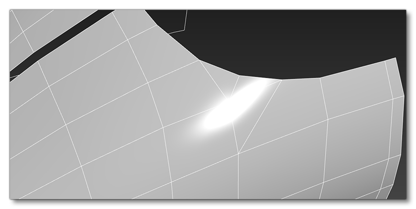
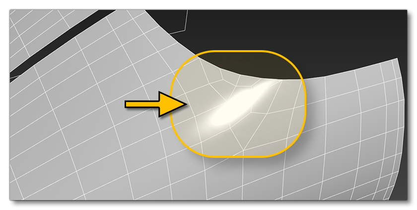
Using quads will also offer superior results on lower resolution meshes when a TurboSmooth modifier is applied too, as illustrated in the following example (mouse over it to see the mesh with the modifier applied):
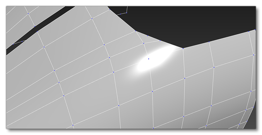
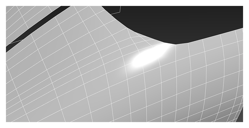
In order to maintain a higher quality mesh and UVs, you should avoid using TurboSmooth modifiers on the exportable mesh. Only use this feature to quickly up-res the mesh to the required resolution, as it will then be collapsed in order to clean it up and remove unnecessary edges and fix any UV distortions.
Increasing Mesh Resolution
In order to get better control over the increase of mesh resolution without relying on TurboSmooth, we recommend that you use the 3DS Max Freeform modelling tools as much as possible. For example, when using the Flow Connect and Set Flow tools to increase resolution of the model we have full control over the poly usage.
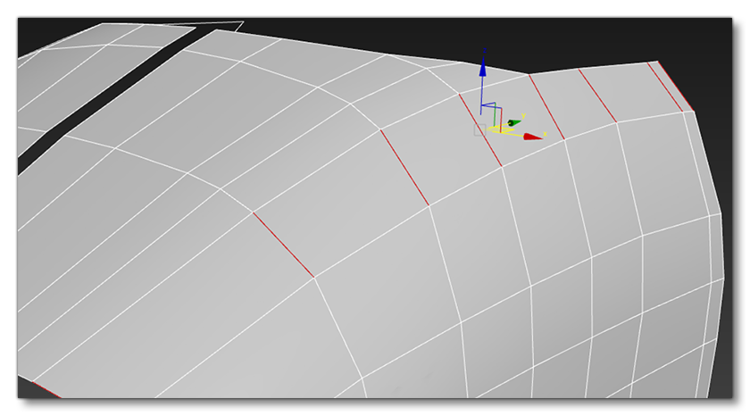
In the following example image we have selected the edge ring:
 We then click on Flow Connect to add a new loop that conforms to the average normal direction of the neighbouring edges:
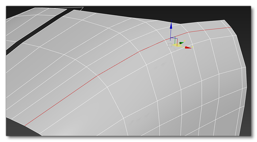
Which gives the following result:
 You would then repeat this process across the rest of the mesh until you have achieved the desired result:
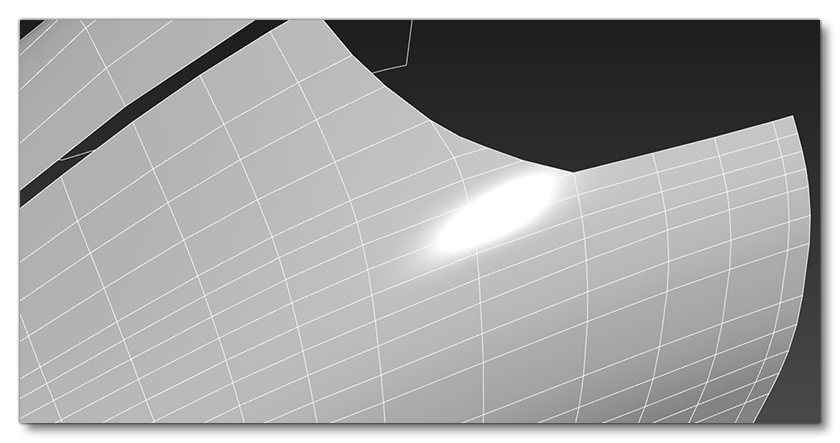 Finally, by using the Set Flow options to tidy the edge spacing, you can remove edges and reintroduce triangles to optimise the mesh:
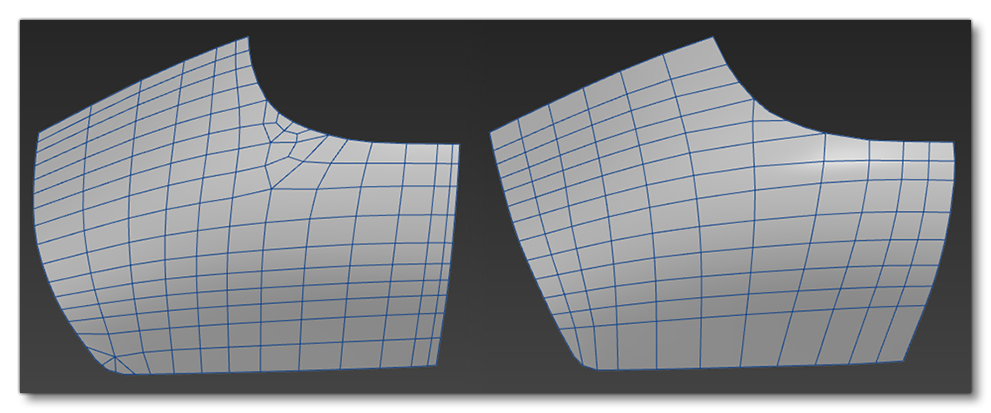
 In the image below you can see a final result, where the one on the left is 334 tris with TurboSsmooth and the one on the right is 241 without TurboSmooth but using the Freeform modelling tools to add geometry manually, giving you a smoother finish:
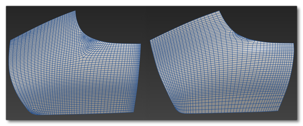
It is worth noting that adding a meshSmooth modifier over the top of the tidied up mesh will give a cleaner final result in the event of an ultra-high resolution LOD, and this is also especially useful when baking normals:
 IMPORTANT! Always ensure that the shape you are recreating is not negatively affected when increasing resolution, and always refer back to the reference when adding or removing geometry resolution to ensure you are not straying from the real plane.
First Pass Results
Following the general principles outlined on these pages, your aim is to finalize a "first pass" of the aircraft exterior model that is accurate in shape and scale, and that has the essential mechanical component animations in place, ie: ailerons, rudder, flaps, landing gear, etc...
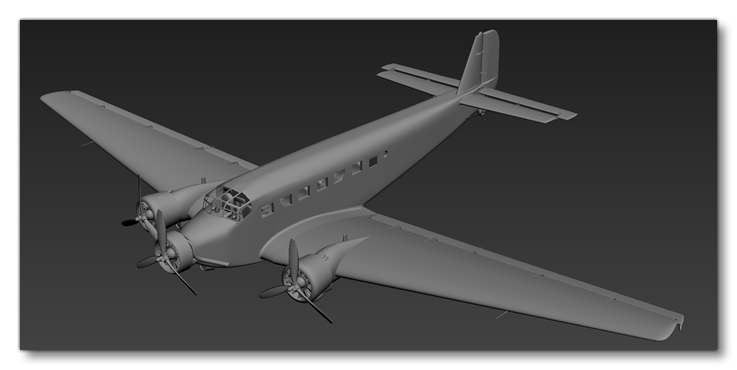
Once you have the first pass done, you would go ahead and configure the aircraft for testing in the game, and once everything has been set up correctly return and give the model and textures a final tweak and polish.