WHEELS
Creating the wheel model is very straightforward and the model should contain some detail, especially around the rims and for the tread. The following image shows a wheel from the DA62 and you can use it as a reference for the kind of detail that should be part of the model, and for what can simply be part of the texture:
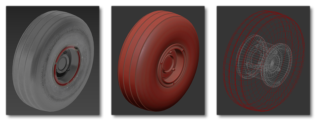
Note that we recommend you model the rim and the tire as two separate objects, since we will be using UV animation on the tire to simulate its rotation and this requires a unique texture and UV mapping, while the rim will be animated using a bone setup as part of the landing gear (this is explained in more detail below).
There are numerous types of wheel that can be used on an aircraft, and they all have different treads and details. If the tread is very detailed, then consider making a high-poly version and baking a normal map from that then applying the normal map to the wheel texture instead of modeling every single groove. More information on how the texture map, UVs and materials for the wheel should be setup are given below.

Low Detail Wheel
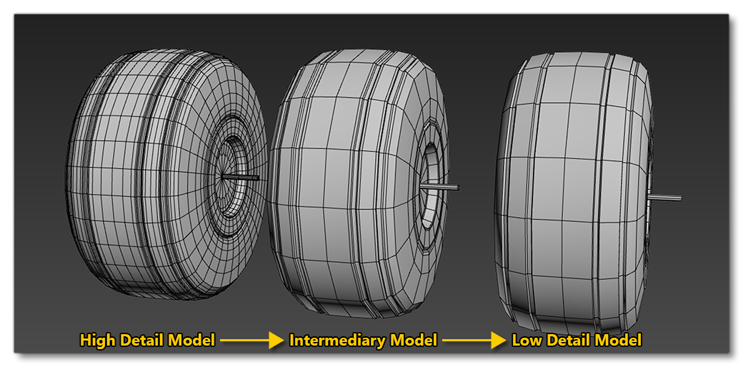
Once you have the wheel modeled in detail, you will also need to add a low-detail version. This is a model with a blurred texture and lower polygon count that will be used by the simulation when the wheel starts to rotate at higher RPMs. To create the blur mesh we recommend that you simply copy the static wheel (tire and rim) and lathe out a shape from it that would allow for a blurred texture using less polygons. Ideally you should aim to reduce the resolution down by approximately 50% for efficiency in the simulation:
Tire Material Setup
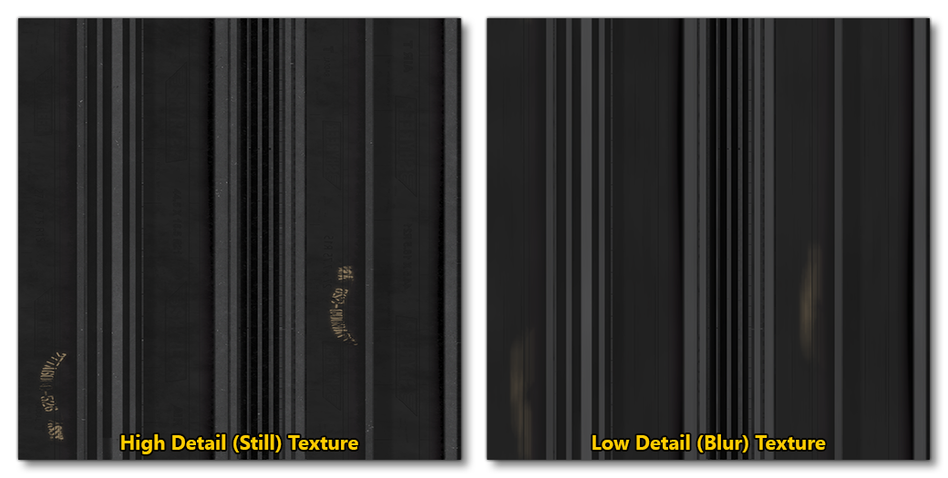
When it comes to the material being used for the tires it should be the Standard material and the only texture that is mandatory is the albedo (Base Color) texture, however you should also supply Occlusion(R) Roughness(G) Metallic(B) and Normal textures to create a fully realistic tire. You should not make one material for all tires, but instead create one material per landing gear per detail mesh. So, if the aircraft has two wheels, that's four materials - left and right low-detail blurred materials, and left and right high-detail still materials:

This is required because wheels are only animated when the aircraft is in contact with the ground and is in movement, so - when landing for example - not all the landing gear will make contact at the same time, meaning the wheels need to be able to rotate based on when they touch down. The image below gives you an idea of how the wheel textures should look in these materials.
Rim Material Setup
The rims are like the tires in that the material used should be the Standard material and the only texture that is mandatory is the albedo (Base Color) texture, however you should also supply Occlusion(R) Roughness(G) Metallic(B) and Normal textures to create a fully realistic rim. Unlike tires, however, you only need a single material for both states of the rim (still and blurred), since animation of the rim is handled differently to that of the tire. This material can be part of a multi-material if required, and can be used for more than just the rims to make the most of texture space.
Tire UV Mapping
In previous versions of the simulation the entire wheel was animated to make it rotate, however in Microsoft Flight Simulator 2024 that is no longer the case and only rims are animated, while the tire is now handled by UV animation. This means that the model and texture setup required for the wheels is simpler. The image below shows how the texture should be UV mapped to work with this new system:
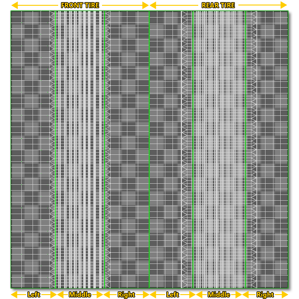
IMPORTANT! You must ensure that your tires do not have symmetrical UVs, otherwise when you go to animate the UVs, the sides of the tire will be rotating in opposite directions. The UV's should also be straight.
The actual animation is set in the material properties, using the V Offset value in the UV Options:
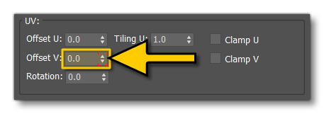
This offset value should be set to 0 on the 1st frame of the animation track, and end on 1 on the 5th frame of the animation track. This means that frames 0 - 4 will rotate the tire texture through 360°. While doing this ensure that the tire object is visible and rotating in the correct direction: it should be rotating anti-clockwise when viewed from the left side of the aircraft.
Finally, make sure that the the wheel animation is added into the animation groups (see here for more information: Babylon Animation Groups):
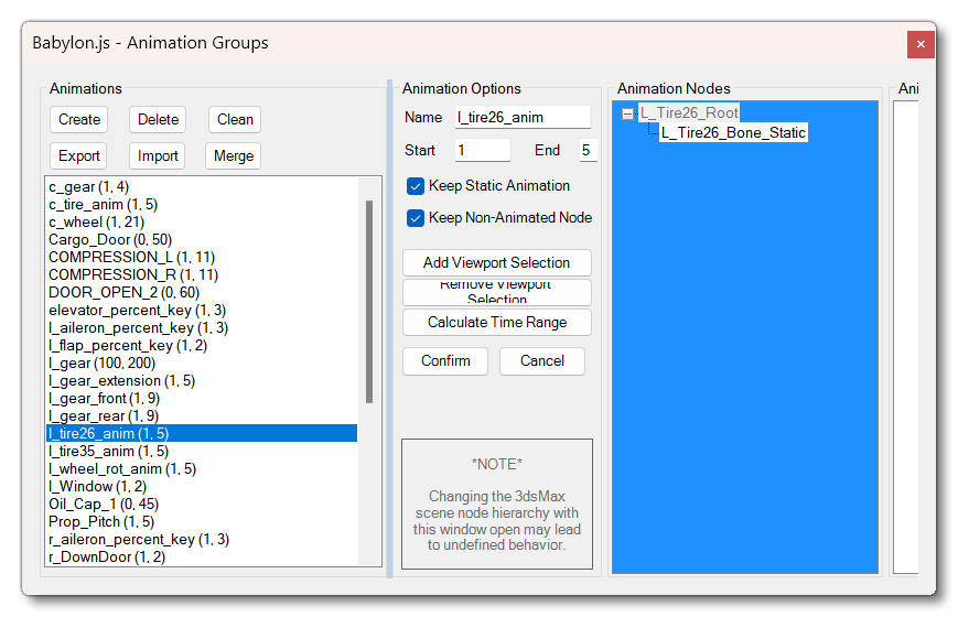
Rim UV Mapping
Depending on your aircraft, the wheel rim can be mapped onto a unique texture or it can be added into the texture that is used for the landing gear, for example here the rim is mapped with the landing gear and landing well textures:
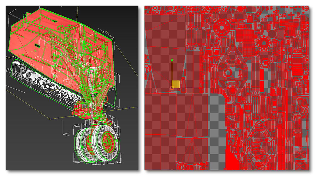
Don't forget to planar map the sidewall of the rims so that - regardless of the mesh resolution - you will get a rounded effect and not a "kaleidoscope" effect, and it's fine to design it so the UVs are all on one texture to be used for both the still and the blurred rims. To get these UVs, you can simply select the relevant part of the rim then use the "Straighten Selection" tool:
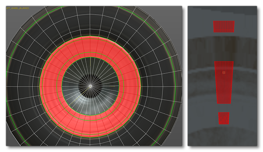
Finally, you would then scale these results up and map them to the correct place on the texture:

Tire Deformation
To make the tires more realistic, they can be deformed when under physical pressure (ie: contact with the ground). This deformation is handled using a skinned mesh of the tire and a few dummies which are then animated in time with the movement of the landing gear. The actual setup is as follows (for each tire):
- Make the tire a skinned mesh with a bone in the center and ensure that the tire model is a child of this bone (which in turn should be a child of the part ROOT).
- Next, add in three helper points at the base of the tire where it would come into contact with the ground.
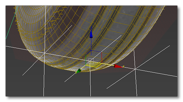 These will be used to animate the wheel deformation: the middle one for the tire compression and the side ones are to stretch out and deform the mesh.
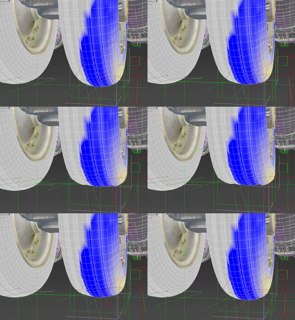
- You should now set the animation to cover the same number of frames as your landing gear compression animation, such that the last frame of the tire deformation coincides with the maximum compression of the landing gear mechanism. For more information on this, please see here: Animating Landing Gear.
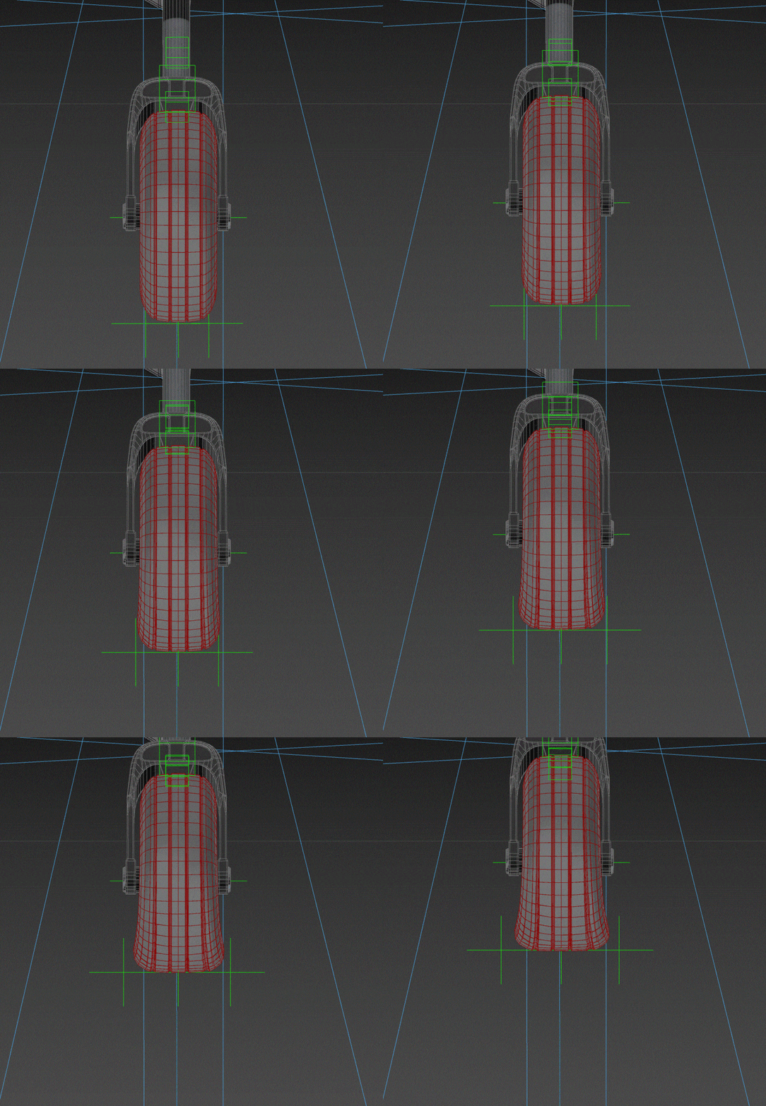
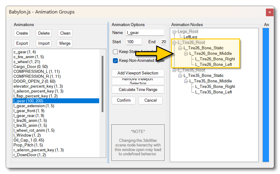
- Finally, make sure that the the wheel root bone is added into the animation groups (see here for more information: Babylon Animation Groups):
As an additional note, your wheels will need to be setup to accept chocks so that these can be used as part of the preflight checks that pilots must perform. For more information on setting these up, please see the following pages:
Rim Animation
Rims are do not use animated UVs and as such will need to be animated in the modelling software. The rims will need a bone which should be a child of the main wheel root bone. To animate the rim in the simulation, you will need to make the rim model rotate 360° over five frames of animation. 0° on the 1st frame of the animation track, and end back on 0° for the 5th frame of the animation track. This means that frames 0 - 4 will rotate the rim model through 360°.
| Frame | Angle |
|---|---|
| 0 | 0° (Neutral Position) |
| 1 | 90° |
| 2 | 180° |
| 3 | 270° |
| 4 | 360° |
While doing this ensure that the rim object is rotating in the correct direction: it should be rotating anti-clockwise when viewed from the left side of the aircraft.
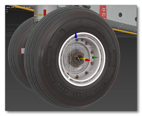
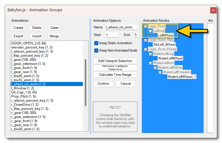
Much like the tires, the rims will need adding into the animation groups (see here for more information: Babylon Animation Groups):
Wheel Collisions
The wheel assembly (as a whole) also requires a collision mesh so that it interacts properly with preflight interactions and other aspects of the simulation. Unfortunately, you can't use the Collision Material parameter for a skinned mesh, and so you will need to make a simple collision mesh above the wheel and brakes parts. This will enable the interactions during preflight and other moments:
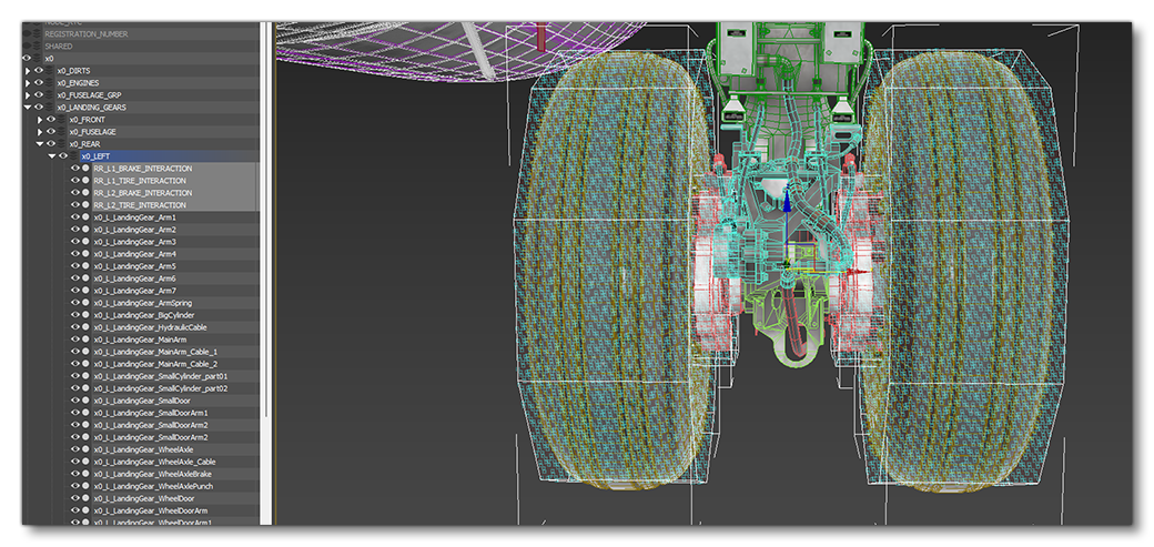
This simple mesh should be using the Invisible material and you should ensure the Collision Material setting is checked. This will ensure that the mesh is recognised as a complex collision mesh in game. With this you avoid any possible difficulty with interactions between the different parts of your landing gear.
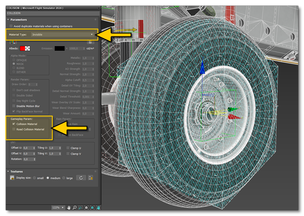
NOTE: This material can be part of a multi-material and can also be used for other collision meshes. You do not need a unique material per-collision mesh.
XML Setup For Animating The Wheel
Both the tires and the rims will need to be added into the Model XML file, so that the simulation knows which nodes are the ones to apply the blurring to when the wheel is in movement. This is done using some of the built in templates as shown in the following example (for left and right wheels - tires and rims):
<Include ModelBehaviorFile="Asobo_EX1\Index.xml" />
<Include ModelBehaviorFile="Asobo_EX1\DefaultConfig.xml" />
<Include ModelBehaviorFile="ASOBO_EX1\ExteriorDefs.xml"/>
...
...
<Component ID="GEARS_Tires">
    <UseTemplate Name="ASOBO_ET_LANDING_Gear_Left_Tire_Template">
        <ANIM_NAME>l_wheel_rot_anim</ANIM_NAME>
        <NODE_ID_STILL>LEFT_WHEEL</NODE_ID_STILL>
        <NODE_ID_BLURRED>LEFT_WHEEL_BLURRED</NODE_ID_BLURRED>
    </UseTemplate>
    <UseTemplate Name="ASOBO_ET_LANDING_Gear_Left_Tire_Template">
        <DISABLE_ANIMATION>True</DISABLE_ANIMATION>
        <NODE_ID_STILL>LEFT_Rim26</NODE_ID_STILL>
        <NODE_ID_BLURRED>LEFT_Rim26_BLURRED</NODE_ID_BLURRED>
    </UseTemplate>
    <UseTemplate Name="ASOBO_ET_LANDING_Gear_Right_Tire_Template">
        <ANIM_NAME>r_wheel_rot_anim</ANIM_NAME>
        <NODE_ID_STILL>RIGHT_WHEEL</NODE_ID_STILL>
        <NODE_ID_BLURRED>RIGHT_WHEEL_BLURRED</NODE_ID_BLURRED>
    </UseTemplate>
    <UseTemplate Name="ASOBO_ET_LANDING_Gear_Right_Tire_Template">
        <DISABLE_ANIMATION>True</DISABLE_ANIMATION>
        <NODE_ID_STILL>RIGHT_Rim26</NODE_ID_STILL>
        <NODE_ID_BLURRED>RIGHT_Rim26_BLURRED</NODE_ID_BLURRED>
    </UseTemplate>
</Component>
It should be noted that when using the landing gear templates for tires and rims, that the rims will need the <DISABLE_ANIMATION> tag to be added, since there will be no UV animation applied to them. You can find information on the appropriate templates from the following pages:
ASOBO_ET_LANDING_Gear_Center_Tire_TemplateASOBO_ET_LANDING_Gear_Back_Tire_TemplateASOBO_ET_LANDING_Gear_Left_Tire_TemplateASOBO_ET_LANDING_Gear_Right_Tire_Template
Related Topics