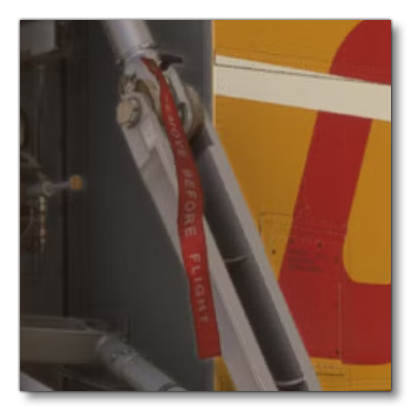
COVERS, CHOCKS, AND PINS
This section goes through the steps required to correctly model additional preflight detailing that should be included with all aircraft in Microsoft Flight Simulator 2024. This is an essential part of the modeling process as removing covers, pins, etc... is required as part of the Preflight Check that pilots should go through with their aircraft before a flight. Note that all the models described in this section are static, can be quite detailed, and should use the Standard material type.
Covers
Each aircraft should have a number of covers that protect delicate and important components and areas from damage or wear from external sources. In the simulation, these elements will be removed during the preflight check and there will be consequences if they are not removed. For example, engine covers will prevent engines from starting, pitot and static covers will prevent some instruments from working correctly etc...
Covers come in varying shapes, sizes and types, and are modeled as simple static meshes that go over (or into) the part they are protecting. The list below gives some broad categories and examples of covers and how they should look in the simulation:
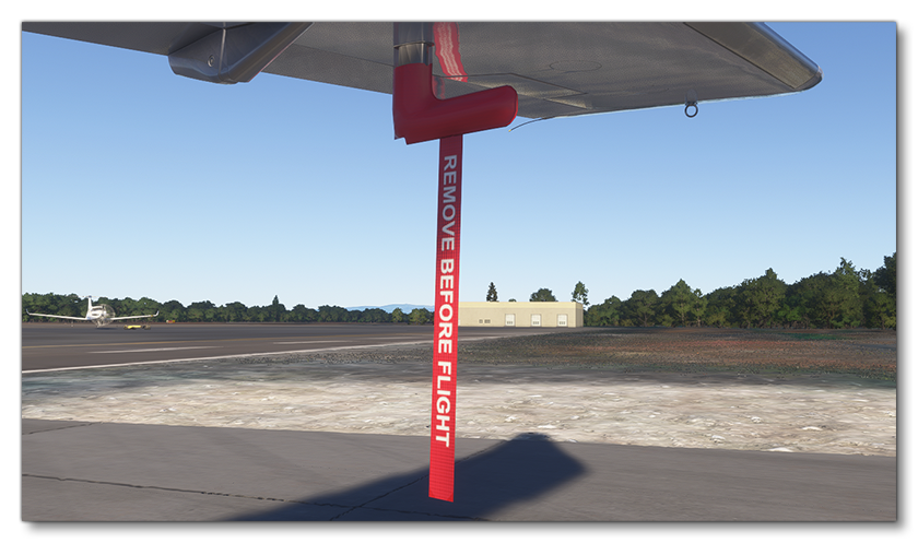
NOTE: Some of the images show a "Remove Before Flight" tag hanging from the various covers. This is a special physics object that is spawned by the simulation and does not need to be modeled. See "Remove Before Flight" Flags for more information.
-
Air Intake Covers
Intake covers come in many different shapes and colors, but for the simulation we recommend that they are either red or orange so they stand out. They can be placed within the engine ports or over the engine intakes:

-
Propeller / Rotor Covers
Propeller aircraft and helicopters have covers that go over the edges of the propeller blades and rotors, and these covers usually have locks with cables to hold the propeller/rotor in place when being used:
 NOTE: For helicopters, blade covers need to fit the lowest blade position - ie: the blade angle when the rotor is static - so that they fit correctly for the preflight checks. These blade covers will need to be skinned to the rotor blade. For more information, please see here: Helicopter Blades
-
Static Port And Pitot Covers
The static cover protects pressure readings by preventing debris entry during ground operations and idle times, and these are typically removed and replaced during preflight checks:

Pitot probes should also have their own cover, which is usually like a kind of "sock" that protects the probe from damage:

Note that you will need to export all your different covers as part of the the correct part being exported so that they are included in each of attached objects used by the different presets for a Modular SimObjects, for example the engine cover should be exported with the engine, the pitot cover with the wing, etc… You should also ensure that the covers have appropriate and unique node names as these will be used in the Preflight XML to show/hide them.
Landing Gear Pins
Landing gear pins - or downlock pins - secure an aircraft's landing gear during parking or maintenance, preventing collapse while on the ground, and must be removed before takeoff for safety. Not all aircraft have these pins, but most do, and they are an important part of the preflight checks for any aircraft to remove them. For Microsoft Flight Simulator 2024 your landing gear should be modeled with holes for these pins and the pins should be added into them and exported along with the landing gear.
NOTE: Most landing gear pins should have a show a "Remove Before Flight" tag hanging from them. This is a special physics object that is spawned by the simulation and does not need to be modeled. See "Remove Before Flight" Flags for more information.
Chocks
Aircraft chocks are wedge-shaped devices made from durable materials such as rubber, plastic, or metal. They are specifically designed to prevent aircraft from rolling or moving unintentionally when parked on the ground, by being placed in front of and behind the aircraft wheels. When creating your own aircraft you do not need to model these items as your aircraft will be using one of the chocks which exist as Included Attachments. However, you will need to set up your wheels to be able to accept having the chock object.
NOTE: Setting up for chocks will require that you have first correctly setup the wheel object as explained here: Wheels

The actual model setup for chocks simply requires an attach-point to be created at the same position as the central animation helper for the tire deformation - as explained here: Tire Deformation - and it should be a child of the deformation node, as shown here (the attach point is the red box):

The rest of the setup is done in the attached_objects.cfg for the common or attachment folder that has the landing gear object in it (which one will depend on whether the landing gear is part of the common root object, or an attachment). In this file you will need to set up the sim attachment like this:
[SIM_ATTACHMENT.0]
attachment_root="SimAttachments/Aircraft_Objects/Asobo_Chocks_02_L250_W270_H85"
attachment_file="model/Chocks_02_L250_W270_H85.xml"
attach_to_model="exterior"
attach_to_model_minsize=1
attach_to_node="ATTACH_POINT_Chocks_F"
alias="Chocks_F"
Be sure to choose the correct chocks from the Included Attachments for the size of the aircraft and wheels (which may need some trial and error). Once you have done this, the chocks need no further setup and should be usable as part of the preflight checks, since all the logic for the interaction is included with the included chocks attachments.
"Remove Before Flight" Flags
Most kinds of covers and pins will have a "Remove before flight" flag on them, to ensure that they are visible and it's obvious that the specific protection measure has not yet been removed from the aircraft.

These flags will be removed at the same time as the item that they are attached to, but for that to happen in the simulation you will be required to add some very specific code to the flight_model.cfg. In this file you will need to add one or more [OBJ_EA1_PITOTFLAG.N] sections (one for each flag object) and then set up the different parameters. For example, the flag shown in the image above has the following setup in the file:
[OBJ_EA1_PitotFLAG.0]
position = -15.5, 5.05, -11.2
size = 0.22, 1.75, 0
linked_behavior_index = 2
surface_relative_position = 0.1, 0, 0
surface_angle = 0, 0, 90
material_guid = E48F59B9-94E0-4CA2-B261-8E5FFFF3CB03
Additional Protective Gear
The covers and other items mentioned on this page are important to include as they make up not only part of the Preflight checks, but also the Wear And Tear systems. Starting a flight and not removing any of the covers or pins will result in problems, for example: engine covers will prevent engines from starting, and pitot or static covers will prevent some instruments from working correctly.
However you can also add optional additional covers and protective gear to the aircraft for realism, even though these will have no consequences if they are missed in the preflight checks (although they should still be included in the checks and removed before flight). One example of these additional covers would be covers placed on the winglets of an aircraft:

Additional Collision Meshes
Some preflight interactions will require an additional collision mesh to make them easier for the user to click on, since the element itself may be small and difficult to get the mouse or controller to detect (for example, landing-gear pins). If the element is a skinned mesh then you will also need to create an additional collision mesh as skinned objects will not react to interactions. In both these cases you will need to create a simple collision mesh using the Invisible material.
NOTE: If you also wish to prevent collisions with the user character - or any other element - then you may also check the Collision Material parameter.
The image below shows how a large and simple collision mesh has been created to contain not only the pitot cover, but also the "Remove Before Flight" tag that will be visible in the simulation (but is not present on the model):

If you are including an additional collision mask for interactions like this, be sure to note the node name as it will be required later, since having an additional collision mesh like this requires a slightly different preflight setup in the code (as explained here: Alternative XML For Small Elements)
Related Topics