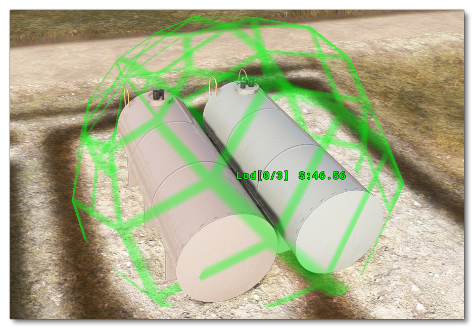
LOD SELECTION SYSTEM
Whether you are creating Aircraft models or Scenery models, an important part of their creation is the correct implementation of LODs and an understanding of how LOD selection system works in Microsoft Flight Simulator 2024.
IMPORTANT! The information on this page is only relevant for packages built with MSFS 2024. Packages built with MSFS 2020 and loaded into the simulation will still follow the legacy LOD rules.
On this page we outline the general rules that govern how LODs are selected throughout the simulation, regardless of what kind of object it is that is being displayed. For more general guidelines on LOD creation, please see the following page:
Screen Size
Instead of using distance from camera to define the displayed LODs, Microsoft Flight Simulator 2024 uses screen space ratio, since objects can vary significantly in scale and shape. To give an example, have a look at this comparison between a Boeing 747 and a Cessna 172:

If you viewed the 747 on screen and saw it as the same size as the Cessna, the 747 would have to be significantly farther away from the camera than the smaller aircraft, and as such it will be at a lower LOD level, yet both aircraft could have approximately the same number of polygons. This helps keep the load on the render engine consistent and maintain performance.
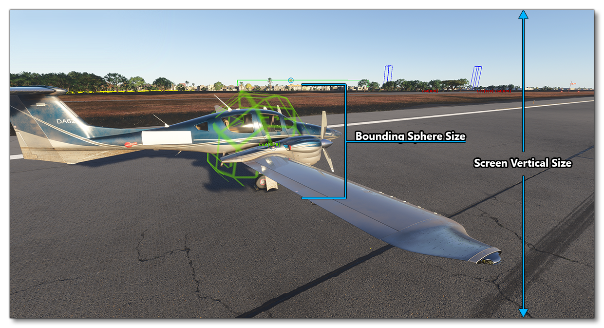
In order to calculate the LOD used, the engine will use the bounding sphere of the model which you can visualise using the Display Bounding Spheres option from the Debug LODs window.

With the bounding sphere shown, you can get an idea of the screen space ratio that is used to calculate the LODs, as it's simply the ratio between the size of this bounding sphere and the vertical size of the screen:

MinSize
As described in the Model Definitions section, each 3D object used by the simulation includes an XML file that describes its various LODs (unless you are using Simplygon to generate the LODs), for example:
<?xml version="1.0" encoding="utf-8" ?>
<ModelInfo version="1.0" guid="">
    <LODS>
        <!-- Highest LOD -->
        <LOD minSize="80" ModelFile="MyModel_LOD00.gltf"/>
        <LOD minSize="30" ModelFile="MyModel_LOD01.gltf"/>
        <LOD minSize="20" ModelFile="MyModel_LOD02.gltf"/>
        <LOD minSize="13" ModelFile="MyModel_LOD03.gltf"/>
        <LOD minSize="8" ModelFile="MyModel_LOD04.gltf"/>
        <LOD minSize="5" ModelFile="MyModel_LOD05.gltf"/>
        <LOD minSize="1" ModelFile="MyModel_LOD06.gltf"/>
        <!-- Lowest LOD -->
    </LODS>
</ModelInfo>
In this file description the minSize attribute is the minimum vertical screen size (in %) of the bounding sphere that is required for the LOD to be displayed (its default value is 0). In the example above, MyModel_LOD00.gltf would be displayed only when the vertical size bounding sphere of the object reaches 80% of the screen size.
IMPORTANT! For performance reasons, the vertical size of the projected bounding sphere is calculated with using various approximations which can make it slightly larger than you may expect for the actual model being rendered.
It is also important to note that in previous versions of the simulation the minSize attribute of the second to last LOD was forced to be greater than or equal to 1. However in Microsoft Flight Simulator 2024 this is not always the case.
Vertex Count Limits
The system described above is not the only thing to consider when it comes to LOD calculations, since it could allow for small models (on the screen) to be much too complex and hamper performance. Therefor other metrics must come into play with the aim of preserving the global vertex density.
The other system that is used in combination with the minSize is to use a data curve that matches the vertex count with a specific minimum screen size. For reference, here is a table that demonstrates the relationship between (approximate) vertex count and screen size when the simulation is using different graphics settings:
| Vertex Count | Minimum Size On Screen | |||
|---|---|---|---|---|
| Ultra | High | Medium | Low | |
| 150 | 0% | 0% | 0% | 0% |
| 300 | 1% | 1% | 2% | 4% |
| 2500 | 5% | 9% | 18% | 36% |
| 5,000 | 7% | 14% | 28% | 56% |
| 30,000 | 18% | 34% | 68% | 136% |
| 60,000 | 25% | 49% | 98% | 196% |
| 150,000 | 39% | 77% | 154% | 308% |
| 250,000 | 50% | 100% | 200% | 400% |
| 500,000 | 71% | 141% | 282% | 564% |
| 1,000,000 | 100% | 200% | 400% | 800% |
| 2,000,000 | 142% | 283% | 566% | 1132% |
In general you should consider the Vertex Count Limit as a modifier of the minSize attribute specified in the XML. Essentially, the effective minSize used by the simulation is the maximum value between that specified in the XML and that calculated from the curve created by the table above.
As a side note, the convention for creating the XML which is used currently by the artistic team behind the simulation, is as follows:
<?xml version="1.0" encoding="utf-8" ?>
<ModelInfo version="1.0" guid="">
    <LODS>
        <!-- Highest LOD -->
        <LOD minSize="7" ModelFile="MyModel_LOD00.gltf"/>
        <LOD minSize="6" ModelFile="MyModel_LOD01.gltf"/>
        <LOD minSize="5" ModelFile="MyModel_LOD02.gltf"/>
        <LOD minSize="4" ModelFile="MyModel_LOD03.gltf"/>
        <LOD minSize="3" ModelFile="MyModel_LOD04.gltf"/>
        <LOD minSize="2" ModelFile="MyModel_LOD05.gltf"/>
        <LOD minSize="1" ModelFile="MyModel_LOD06.gltf"/>
        <!-- Lowest LOD -->
    </LODS>
</ModelInfo>
This is basically the artist saying "we trust that the LOD Selection System will always choose the best LOD for the distance from the camera". Doing things this way means that the artist doesn't have to worry as much about finding the optimal minSize value, and most of the time LOD limits mean that there will be a swap to the next LOD before the given minSize is met anyway. You do not have to do this with your own aircraft, but if you've followed the LOD Technical Information guidelines correctly and setup your models correctly, this is a generally good approach.
Additional Information
The vertex count and the minSize are the two main metrics which will decide the LOD that is displayed in the simulation, but there are a few other things that will be taken in to consideration:
- the last LOD
minSizevalue is always forced to 0.5%. - The second to last LOD
minSizevalue is always greater than or equal to 1%, unless it is the user aircraft.
As a consequence of the two points mentioned above, an object that has a screen size of less than 0.5% is never displayed. Further things to be taken into consideration are as follows:
- When an empty glTF (which contains no mesh) is used as an attachment base for a Modular SimObject, it's
minSizewill always be set to 0.0005% to ensure that the object doesn't just disappear, and an arbitrary bounding sphere with a 1m radius is assigned to it. - The root element of the user aircraft is always displayed at its most detailed LOD / LODx0
IMPORTANT! For modular SimObjects, any attachments made to this root element will be affected by the LOD selection system.
Example
To aid with understanding the way LODs are selected, consider the following example where we have the following model definition (approximate vertex counts are indicated in the XML comments):
<?xml version="1.0" encoding="utf-8" ?>
<ModelInfo version="1.0" guid="">
    <LODS>
        <!-- Highest LOD -->
        <LOD minSize="80" ModelFile="MyModel_LOD00.gltf"/> <!-- LOD0, 300,000 vertices -->
        <LOD minSize="60" ModelFile="MyModel_LOD01.gltf"/> <!-- LOD1, 100,000 vertices -->
        <LOD minSize="45" ModelFile="MyModel_LOD02.gltf"/> <!-- LOD2, 40,000 vertices -->
        <LOD minSize="30" ModelFile="MyModel_LOD03.gltf"/> <!-- LOD3, 20,000 vertices -->
        <LOD minSize="20" ModelFile="MyModel_LOD04.gltf"/> <!-- LOD4, 10,000 vertices -->
        <LOD minSize="0.5" ModelFile="MyModel_LOD05.gltf"/> <!-- LOD5, 5,000 vertices -->
        <LOD minSize="0.2" ModelFile="MyModel_LOD06.gltf"/> <!-- LOD6, 1,000 vertices -->
        <!-- Lowest LOD -->
    </LODS>
</ModelInfo>
With these values, running the simulation on the High graphics settings, we have the following:
- LODx0: The vertex count rules indicate that for this number of vertices, the
minSizeshould be at least 110% - this value will be used instead of the 80% of the XML - LODx1: The vertex count rules indicate that for this number of vertices, the
minSizeshould be at least 63% - this value will be used instead of the 60% of the XML - LODx2: The vertex count rules indicate that for this number of vertices, the
minSizeshould be at least 40% - the value of 45% indicated in the XML will be used - LODx3: The vertex count rules indicate that for this number of vertices, the
minSizeshould be at least 28% - the value of 30% indicated in the XML will be used - LODx4: The vertex count rules indicate that for this number of vertices, the
minSizeshould be at least 20% - it is the same value as that indicated in the XML, which will be used - LODx5: Because the second to last LOD
minSizevalue is always greater than or equal to 1% - this value will be used instead of the 0.5% of the XML - LODx6: Because the last LOD
minSizevalue is always forced to 0.5%. - this value will be used instead of the 0.2% of the XML
Putting all this together, we can create a "transformed" model XML file which adequately reflects the actual minSize / vertices relationship:
<?xml version="1.0" encoding="utf-8" ?>
<ModelInfo version="1.0" guid="">
    <LODS>
        <!-- Highest LOD -->
        <LOD minSize="110" ModelFile="MyModel_LOD00.gltf"/> <!-- LOD0, 300,000 vertices -->
        <LOD minSize="63" ModelFile="MyModel_LOD01.gltf"/> <!-- LOD1, 100,000 vertices -->
        <LOD minSize="40" ModelFile="MyModel_LOD02.gltf"/> <!-- LOD2, 40,000 vertices -->
        <LOD minSize="28" ModelFile="MyModel_LOD03.gltf"/> <!-- LOD3, 20,000 vertices -->
        <LOD minSize="20" ModelFile="MyModel_LOD04.gltf"/> <!-- LOD4, 10,000 vertices -->
        <LOD minSize="1" ModelFile="MyModel_LOD05.gltf"/> <!-- LOD5, 5,000 vertices -->
        <LOD minSize="0.5" ModelFile="MyModel_LOD06.gltf"/> <!-- LOD6, 1,000 vertices -->
        <!-- Lowest LOD -->
    </LODS>
</ModelInfo>