MODELING TECHNICAL INFORMATION
This section lists some general modelling information that you should be aware of when creating aircraft and scenery models for Microsoft Flight Simulator 2024. It should be noted that the simulation uses a modified glTF format for models, which is discussed on the following page:
In-Sim Graphics Settings
When switching graphics settings in the simulation, Microsoft Flight Simulator 2024 changes certain properties related to models, so you need to be aware of the following:
- Texture quality settings reduce the resolution of textures. This affects visual quality when viewing an object in close-up and significantly reduces memory used. You can find more information on this from the section on Reviewing Texture Quality And Memory Usage.
- Object LOD quality settings change the "minSize" properties of LODs. Please see the LOD Selection System page for more information. In general, we recommend tweaking your LODs in the "high" quality setting, which is neutral for LOD selection (meaning a LOD with 50% "minSize" will switch at 50% size on screen), and reduces the quality of only some textures.
In-Sim Model Optimization
The goal for model optimization is to reduce CPU/GPU costs, in both execution time and memory, while retaining an as high as possible visual quality. Execution time and memory cost is often a trade-off. A primary example of that is the creation of several LODs. Having a single model LOD is optimal for memory. However, execution time is poor when viewing the model from far away. Because of this, it is necessary to create multiple levels of detail for all of your models, where each level of detail performs better than the previous, starting at the first LOD, typically named "LOD0" or "x0". For general guidelines on modelling LODs, please see here:
The Modeling Scenery page outlines in more detail some of the factors that can be used to optimise your static models, and the page on Scenery LODs goes into more detail on how to generate them correctly. For aircraft, see the sections on the Airframe and the Cockpit as well as the pages that cover Aircraft LODs. The rest of this section contains information that is general and should be applied to all models, regardless of what they will be used for.
Instancing
It is worth noting that the Microsoft Flight Simulator 2024 engine will make use of "instancing" when rendering your models within the scene. This means that if you place the same model 10 times in the same scene, then all 10 of these model "instances" will be batched into a single draw call, saving on performance.
The caveat to this is that it's only applicable to non-skinned meshes, and a model that uses a skinned mesh will not be instanced. Additionally, if a model has some skinned meshes and some non-skinned ones, then the non-skinned ones will be instanced, even though the skinned ones are not.
Excess Vertices In Your Models
When creating your models you want them to be as optimised as possible, therefor you should strive to have only the minimum number of vertices, ensuring that those vertices are essential to the model topology at any given LOD. In general, we recommend that you create your initial model with less details and vertices as a first step, and then check it in the simulation to see how it looks and what the performance metrics are. You can then go back to your modeling tool and add more vertices/polygons that are clearly missing in further steps.
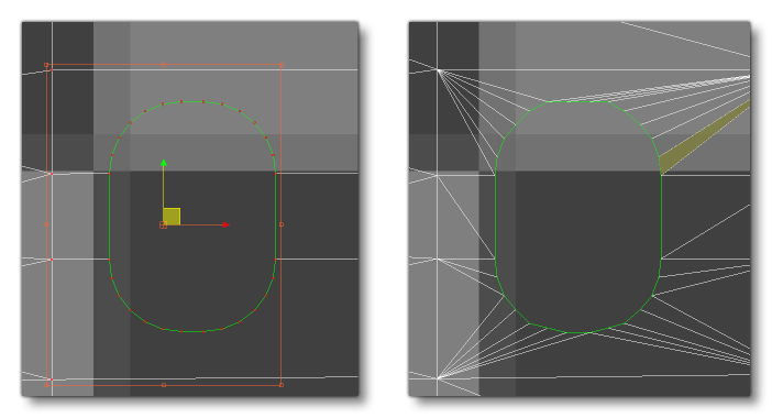
A common culprit for creating performance issues due to excess vertices is the creation of geometry decals for things like aircraft liveries or dirt and grime effects. These are usually created by duplicating the underlying object geometry, and then applying some cuts or booleans along with a little push/inflate so it shows over the "base" mesh. However this will very quickly push up the vertex count and cause issues with the LOD Selection System. As such, these decal meshes can be more heavily optimised, for example, the following image shows a decal mesh (in black) taken from a wing with numerous details:

After optimisation this mesh will have a much simplified geometry which will do the job perfectly when viewed in the simulation, while still being optimal, as shown below (in black):

Finally, on the theme of vertex count, don't forget to apply Weld Surfaces (3DS Max) or use the Weld Modifier (Blender) with all the geometries of your model when you're nearing the end of the modeling process, since it's easy to miss isolated or duplicated vertices. During this clean-up pass you should also try and remove all polygons that will never be visible to the user, since it's easy to forget that some polygons are there, but just out of sight.
Model According To View Distance
While creating your models, it is always a good idea to zoom out regularly and observe the object at a distance which is approximate to that at which the object will usually be seen when placed in the simulation. You want to be modelling only the details that will be visible to the user at that distance, and you need to be aware that modeling a highly detailed object just because the user could move the camera close enough to observe it, is not a good reason to make the model that detailed. The only exception to this is if the object is something that user has to move close to to interact with it.
In general, the assets that need highly detailed geometry are as follows:
- User Aircraft - Aircraft that can be flown by the user need very detailed geometry since aircraft are the stars of Microsoft Flight Simulator 2024. In this version of the simulation it's especially important given the addition of preflight checks, where the player can interact with the exterior of the aircraft, but in general aircraft should be as detailed and accurate as possible.
- Service Vehicles and Characters - All vehicles and characters that are related to aircraft parking spots, aprons, and ground services, should be as detailed as possible within the limits, since these will be viewed up close and often.
- Feature props - Some props, like jetways, runway lights, taxiway signs, etc... should also use detailed models.
Some examples of assets that don't need quite so much detail in their geometry are buildings, vegetation, general world traffic vehicles, traffic aircraft, POIs, etc…
When you're zooming out in your modeling software and looking from an appropriate reasonable distance, you should pay attention to the vertices or edges of smaller details. If they are so close to each other that they blend together visually, then it means you can probably simplify them. This can also be checked in the simulation by enabling the Wireframe debug option. This gives you a wireframe view of the model in the simulation and, again, when edges seem to blend together or are so close that the model looks solid, then simplification of that area necessary:

In the image above the rivets have way too much detail for the size at which they will normally be seen, and as such these could be simplified, or even turned into decals.
UV Precision
When you create a package for Microsoft Flight Simulator 2024, models are processed by the package tool into compatible gLTF files that are optimised for use within the simulator. Part of this optimisation process involves storing the UV data as 2-byte floating point numbers, instead of regular floats, to save on memory usage. What this means is that UVs will have less precision, and if you have a UV that tiles too much, this lack of precision will become very noticeable. You can see this illustrated in the image below, where the left image is the original, and the right is after processing:
 To resolve this issue, you should try and maintain the UV values as close to 0 as possible, since the further from that value the less precise the values will be. In general we recommend maintaining the UVs between 0 and 1, but if you require a texture that tiles, we understand that this may not be possible. In those cases, one trick is to shift the UVs to use negative values, for example, a UV of 0 to 10 could be shifted to be a UV of -5 to 5, and so keep precision errors to a minimum.
Tangents
When a mesh is imported for the first time, Microsoft Flight Simulator 2024 always calculates the tangents. In order to avoid any issues with the normal map, ensure the mesh has a smooth surface and no connected vertices overlap in position or UV space.
For skinned meshes, the tangents are calculated using the default position of the mesh (the T-pose). In the Babylon Exporter, the T-pose is the pose at frame 0. To ensure no problems occur, a good convention would be to start all animations at frame 1 or later.
Collision Meshes
Many objects in the Microsoft Flight Simulator 2024 world are required to detect collisions, whether it's a cockpit button with the user mouse cursor, or a scenery object with an aircraft. You can find details on how these mesh collisions can be set up from the following pages:
- Scenery Collision Handling
- Airframe Collision Meshes
- Cockpit - Collision Meshes
- Cockpit - VR Helpers
Performance Metrics
Below you can find a list of the different metrics that need to be considered and optimised when creating landscape elements. These metrics apply to individual objects (buildings, landscape features, etc...) but are also very important when considering the performance of a large asset like an entire airport. So, for optimal performance, all of the following metrics should be kept to the minimum possible values:
- Texel Count: This is the number of texels (pixels) used by the combined textures. This is a rough indication of memory usage, though different GPU formats will have different memory consumption characteristics. When the package tool compiles a texture, it compiles it to a GPU-ready format (
*.ktx2). The size of this file is the size it will have in GPU memory. you can find additional information on this file format here: KTX2 And KTX2P Files - Material Count: This is the number of materials used. This number, multiplied with the number of meshes using them, is a rough estimation for the number of draw calls. Mesh instances with the same material are grouped in one draw call.
- Mesh Object Count: This is the number of meshes in the element. This, multiplied with the number of materials used, is a rough estimation of the number of draw calls.
- Vertex Count: The number of vertices in the element.
- Face Count: The number of faces (triangles) in the element.
- Skinned Vertex Count: The number of skinned vertices. Skinned vertices use more memory and GPU time than regular vertices.
- Skinned Face Count: The number of skinned faces.
- Texture Count: The number of textures used.
- Bone Count: This is the number of nodes used as bones in skinned meshes. In Microsoft Flight Simulator 2024, this is the entire hierarchy of all the bones used by a skinned mesh, up to the last common ancestor (the "root" node of the skeleton). These bones cost memory in addition to the node they represent.
- Node Count: This is the number of nodes. This translates to objects such as meshes, dummies and helpers in 3DS Max.
- Collision Vertex Count: The number of vertices used for collision detection.
- Collision Face Count: The number of faces used for collision detection.
The table below gives a basic overview of whether these metrics affect the CPU or GPU (or both):
| Metric | GPU Time | GPU Memory | CPU Time | CPU Memory |
|---|---|---|---|---|
| Vertex And Face Count | ||||
| Skinned Vertex And Face Count | ||||
| Collision Vertex And Face Count | *On Raycast |
|||
| Node Count | ||||
| Bone Count | **If Moved |
|||
| Material Count | ||||
| Mesh Object Count | ||||
| Texture Total Size |
* Collision vertices and faces only consume CPU time when they are used for collision detection. This variable cost depends on the situation. It is usually not very high, but minimizing them is recommended.
** Bones only consume CPU when they move, or when their parent hierarchy moves. This is to recompute their world-space matrix.
Animation Guidelines
Below you can find a short list of recommendations for any part of your objects that are animated, describing how best to create the animations as well keep them optimised when imported into Microsoft Flight Simulator 2024.
-
Minimize Skinned Meshes
When you compare an object with a skinned mesh to regular objects, it is found that they consume significantly more CPU cycles and memory, especially compared to previous versions of the simulation. Therefor it is important that you use them only if mesh deformation is absolutely necessary. Even then, you should aim to remove it as soon as the LODs permit it as on lower resolution LODs it won't be noticeable.
-
Minimize Bone Count
You should aim to limit bone count when possible, striking a balance between decent quality animations and more optimised bone structures.
-
Minimize Animation Count
As you create your model and add and test animations, make sure to clean the asset animation list periodically. You want to remove any unnecessary or unused animations to save memory.
-
Limit Bone Affect Limit
It is important to note that the bone affect limit for a skinned object is 4, so a vertex can't be constraint by more than 4 bones.
-
Share Animations
When modeling objects with the same - or similar - shape, sharing animations between them will optimise things a lot. This will require that the animations and meshes are exported independently, and then the animations will be merged into the objects using the model XML files.
-
Modular Aircraft Animations
If the part being animated is part of a modular SimObject, the skeleton of the part must not be linked to the main skeleton. It should have its own main "root" bone, which will then be merged at the (0, 0, 0) of the final SimObject.
-
Animations Length
The simulation engine is capable of interpolating the movement between the first frame and the last frame of the animation. As such, unless the movement is non-linear, you do not need to animate the movement over all 300 frames and bake it into the model.
Animation And LODs
If your SimObject has any animated elements then it should be noted that the Microsoft Flight Simulator 2024 engine will perform certain optimisations on them based on the LOD Selection System:
- As objects get further from the camera, animations will begin to "frame skip" and instead of updating every frame, they will update every N number of frames, where the exact value will depend on the actual distance from the camera. So, for example, a 100 frame animation may play 1 animation frame for every simulation frame when up close to the camera, but then it may play 1 animation frame for every five simulation frames when far away from the camera (frames are interpolated so it would play frames 1, 5, 10, 15, etc...).
- When the object is considered as being less than 1% of the screen size then the animation will no longer be shown and the object will appear static.
Related Topics