WHEELS AND CONTACT POINTS
This page details how to setup and configure the contact and friction models for your aircraft inMicrosoft Flight Simulator 2024. These values can all be set in the SimObject Editor from the Contact Points section of the Flight Model tab:

After selecting this panel it is recommended that you enable the Ground debug window, which will show information about any defined contact points, while also drawing them in the simulation. Each contact point is represented by blue boxes, and from each box a white line will be projected to the nearest ground surface (the line represents the surface normal). Wheels will also be represented in this view as yellow boxes with an additional green box for the contact force:
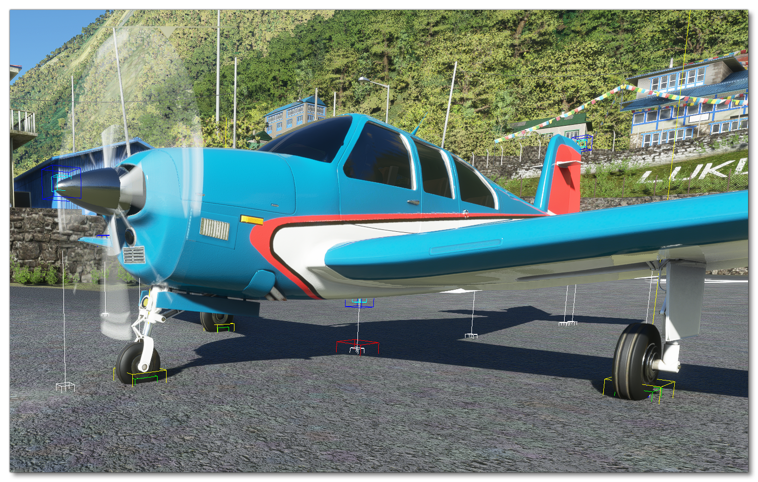
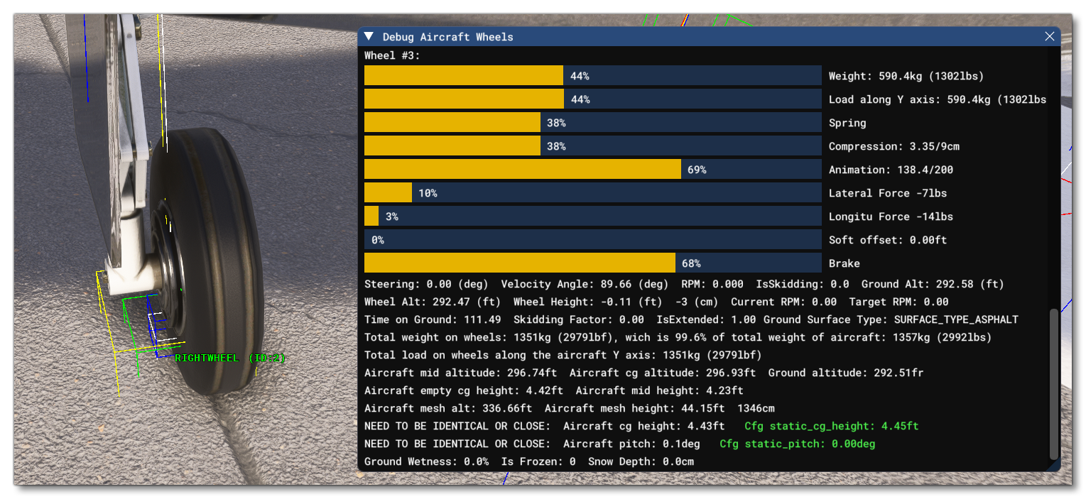
We also suggest opening the Wheels debug window which can be used to help understand the results of the data set you'll be editing for each wheel, which will be the first contact points you should define:

Adding Contact Points
In the SimObject Editor, on the left, you'll see all the defined contact points for the aircraft, and you can add or remove contact points using the + and - buttons at the bottom of the editor. When working on a new aircraft, you'll need to start by adding in the contact points one at a time, usually starting with the wheels and positioning a minimum of 8, as follows:

When adding contact points, you should set up the wheels first and for those you'll need to set up all - or most - of the following parameters:
- Name - The unique name of the contact point.
- Type - Sets the type of contact point.
- Pos - The position of the contact point/wheel relative to the center point of the aircraft. Note that this is made a lot easier if you enable the Gizmo tool and then position the points visually.
- Crash velocity - The maximum velocity at which the wheel will work before being considered a crash.
- Brake - The brake type for the wheel.
- Wheel radius - The wheel radius.
- Wheel steering angle - The maximum angle the wheel can be turned when steering.
- Static compression - This sets the landing gear compression when the airplane is on the ground with all the weight compressing the gears.
- Max to static compression - This sets the maximum to static compression ratio. The higher this ratio is, the "stiffer" the suspension will be, but the higher the loads it can absorb before hitting maximum travel.
- Damping ratio - This represents a ratio of how much energy is lost upon impact.
- Extend time - The time required for the wheel to be extended from the aircraft.
- Retract time -The time required for the wheel to be retracted into the aircraft.
- Sound ID - The ID of the sound effect to use.
- Airspeed Retraction Limit. - The airspeed at which the landing gear needs to be retracted.
- Airspeed Damaged - The airspeed at which the landing gear will be damaged if not retracted.
- Exponential Constant - This allows you to change the spring reaction curve.
These parameters are all set using a single entry in the [CONTACT_POINTS] section of the flight_model.cfg file, which follows this format:
point.[number] = name, class, long_pos, lat_pos, vert_pos, crash_velocity, braking_enum, wheel_radius, steer_angle, static_compression, max_to_static_compression_ratio, dapting_ratio, extend_time, retract_time, sound_enum, airpseed_limit, airspeed_damage, exponential_constant
Note that the contact between a wheel and the ground is esentially the contact between two planar surfaces, however only a point is simulated. Therefor, in order to give the best stability to the plane, we recommend that the wheel points are positioned at the exterior limits of the wheel's triangle.

Another thing to note is that the compression parameters are displayed in the debug window, and you can use the visual feedback to adjust the compression ratios and distances so that the suspension is compressed between 30% and 50% when standing on the runway. Pay particular attention to the pitch of the aircraft when sitting on the landing gear, and ensure that it is correct when parked - a pitch that is too high or too low will negatively impact stability during take-off and landing.
A correctly positioned wheel contact point should look something like this:
You can then position the other contact (scrape) points so that they are aligned correctly with the aircraft model. These points are set similarly to the wheels but most of the fields can be left at the default values shown in the editor (ie: unset), as you only need to edit:
- The name
- The type (scrape point)
- The position
- The crash velocity
Note On Tailwheels
The simulation code can use two different calculations to define when a wheel contact point is a tailwheel or not. This is done using the tailwheel_algo_detection parameter in the contact points section of the flight_model.cfg. By default the "Legacy" method will be used in all cases except for deciding if an aircraft is correctly configured for the user to fly it in a career activity, but setting this parameter to "Modern" will instead use the modern calculation in all cases.
Legacy Tailwheel Calculation
An aircraft is considered as having a tailwheel using the legacy calculation when:
- The wheel is on the center of the longitudinal axis, ie: the X position is 0.
- The wheel contact point is behind the Datum Reference Point, ie the Z position is less than 0.
When both these conditions are met, the wheel is considered as a tailwheel, however this method is problematic with aircraft that are setup in a non-standard way with a datum reference point further forward or backwards than the aircraft CG.
Modern Tailwheel Calculation
For an aircraft to be considered as having a tailwheel, the modern calculation does not use the Datum Reference Point and instead uses a combination of factors related to wheel size and aircraft CG. This is done as follows:
- From the list of contact points in the
[CONTACT_POINTS]section of flight_model.cfg, determine the largest radius between all of the contact points defined as wheels (this value comes from position 6 of thepoint.Ndefinition). - The list of contact points is then parsed again to determine the minimum longitudinal position between all of the contact points defined as wheels (this value comes from position 1 of the
point.Ndefinition) and that have a radius the same as that of the largest radius discovered in the previous step. - If the minimum longitudinal position of a wheel that is found is greater than the
empty_weight_CG_positionZ position value, then the aircraft is considered as having a tailwheel.
Note that even if the tailwheel_algo_detection parameter is set to "Legacy", the modern tailwheel detection calculations will be used to find the tailwheel when the aircraft is being used for a Career Activity. It is also worth noting that using the "Modern" tailwheel calculations will also include the tailwheel in the Wear and Tear system.
Note On Advanced Ground Contact Model
With Microsoft Flight Simulator 2024, a new contact model was created to better simulate wheels and how the aircraft reacts when they are in contact with the ground. This system can be disabled/ignored by simply omitting the parameters mentioned below.
To correctly set up the new contact model, you should start by setting the ground_new_contact_model_up_to_speed_lateral and ground_new_contact_model_up_to_speed_longitudinal parameters. These parameters set the aircraft speed to be used to calculate the lateral and longitudinal friction for the landing gear when on the ground (whether stationary or moving). Lateral friction is for simulating sideways friction when turning, dealing with cross-winds, etc... while while longitudinal friction affects breaking, forward air resistance, ground friction on slopes, etc... Setting very high values for these parameters will result in only the new contact model being used.
To effectively use these parameters you should do the following:
- Enable
enable_high_accuracy_integrationto get the simulation to take micro movements into consideration. - Set
ground_new_contact_model_gear_flexto 1 / aircraft weight and then fine tune the value through tests. - Set
ground_new_contact_model_gear_flex_dampingto approximately 1% of the aircraft weight and then fine tune the value through tests.
NOTE: Using very large values will make the landing gear so flexible that it will become very unstable and generate extremely exaggerated/unrealistic results. - Set the
ground_new_contact_model_up_to_speed_lateralandground_new_contact_model_up_to_speed_longitudinalparameters to 10000 to ensure that the new contact model will always be enabled. - Setting the lateral and longitudinal friction will initially cause the aircraft to get very "sticky" at high rolling speeds. To resolve this, you should edit the
ground_new_contact_model_rolling_stickynessparameter. Start with a value of 0.5 and then reduce it if the rolling still feels too sticky, or increase it if the rolling does not feel sticky enough.
NOTE: You may wish to check that theempty_weight_CG_positionis at the correct height as it will heavily impact ground rolling.
Retractable Floats
If your aircraft model is set up with the animations for retractable floats, then there are a couple of import things that you should know in relation to getting them to work correctly within the simulation.
To start with, you must define a "wheel" contact point as well as the "float" contact points in order for the floats to be evaluated as part of the retract/extend process. This contact point can be placed in a position where it does not interfere with the operation of the aircraft.
Once you have the contact points set up, the animations themselves will be controlled using the following events and SimVars:
- Events:
RETRACT_FLOAT_SWITCH_INCandRETRACT_FLOAT_SWITCH_DEC - SimVars:
RETRACT FLOAT SWITCH,RETRACT LEFT FLOAT EXTENDED, andRETRACT RIGHT FLOAT EXTENDED
Related Topics