JETWAYS
A jetway is usually composed of two objects:
- the jetway itself, which is a SimObject
- a jetway link, which is a Scenery Object connecting the jetway to a building
Note that the jetway link is optional, and that the legacy (FSX) method of having the jetway itself be a Scenery Object is deprecated.
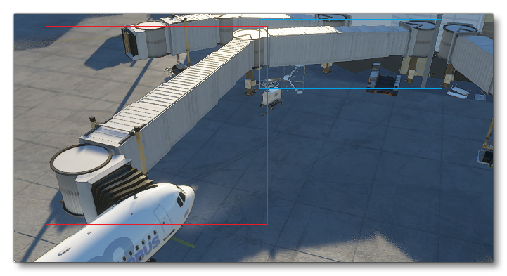
The image below illustrates a typical jetway - on the left, in the red rectangle - and its associated jetway link - on the right, in the blue rectangle - connected to an A320 Neo in Microsoft Flight Simulator 2020:
Details on how to place a jetway and its optional link are available on the Jetway Objects page. You can also find an example Jetway in the Samples folder: Jetway
Jetways And Jetway Links Requirements
A Jetway Link must be a SceneryObject, and should match the associated jetway. More precisely, this means the end of the link that will connect to the jetway should be at the same altitude as the jetway itself.
A jetway link can have an optional single IK chain named IK_MainHandle (see the section IK Chains below). If defined, the End Node of the chain will try to reach the position (0,0,0) of the actual jetway, while keeping the same altitude offset relative to the ground as in its default position. This IK chain can be very useful to adapt a single model of link to various distances from a building to the jetway, by extending and rotating its parts.
A jetway should be a SimObject, with its position (0,0,0) being the bottom of a fixed pilar part, to which a link can connect itself. It should also use three specific IK chains (see the section IK Chains below for details), and six specific model behaviors and animations (see the section on Animating The Hood, below):
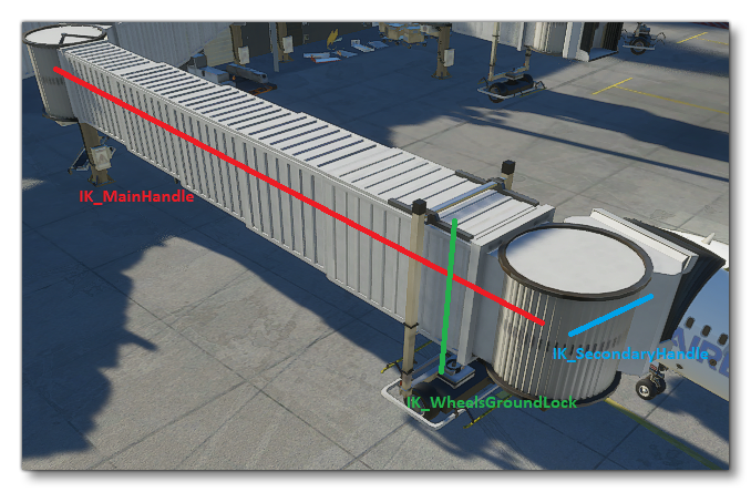
The IK chain named IK_MainHandle should have a Start Node at some fixed position of the jetway, and an End Node in the middle of the "head" of the jetway (i.e. the rotating cylinder that gets close to the aircraft). The IK chain named IK_SecondaryHandle should have a Start Node in the middle of the "head" of the jetway, and an End Node on the contact point that will touch the aircraft. Also, its nodes should only use IK rotations and no IK translation. End Nodes from both IK_MainHandle and IK_SecondaryHandle should be placed such that, when properly connected, they are at the same altitude as the bottom of the aircraft door. Note that the Nodes of the IK_SecondaryHandle chain should not be part of the IK_MainHandle chain, except possibly for the Start Node of IK_SecondaryHandle that could be the End Node IK_MainHandle (though we recommend having the secondary start be a child of the main end).
The IK_WheelsGroundLock chain controls the height of the wheels, in order to stay on the ground during jetway movements. Its End Node should be on the ground between the wheels.
Like any other SimObject, a Jetway can have Model Behaviors. Moreover, a jetway should have six specific animations controlled by six specific model behaviors in order to properly animate the hood, and adapt it to any aircraft shape. This is detailed in the section on Animating the hood, below.
You can find information on setting up the necessary chains in the model XML from the page dealing with the <IKChain> and <IKConstraint> elements.
Model Creation For IK Chains
Here are some considerations when creating a model with parts that will use IK chains:
- When moving through the IK system, a Node will move directly (translating and/or rotating), bringing all its descendants in the hierarchy with it. Usually, jetway (or jetway link) parts that move through IK will not be deformed, which means skinning is not necessary to move the meshes of the parts. Since skins also have a higher performance cost, we recommend to skin only the hood of a jetway, and not its other parts, if possible.
- When a jetway or jetway link has multiple LODs, an IK chain needs to be synchronized when switching from one lod to another. To make sure the synchronization works properly, please respect the following constraints. First, make sure each chain of nodes has the same Start and End node in each LOD, and the same intermediate nodes in the chain (going up from End to Start, parent-to-parent). Second, the Start node of each chain should also have a parent node that is common across LODs, and thus Start nodes should not be directly in the scene without an actual parent Node.
Animating The Hood
The hood of a jetway can generally be deformed while animated, trying to match the shape of the aircraft. In order to have a better result with various aircraft shapes, six specific animations should be created, which will then be played through to match the data of the aircraft.
If all aircrafts and all jetways use the same standard of animations and data, this will result it better hood animation for any combination aircraft-jetway, even if coming from different companies.
Creating The Proper Hood Animations
The six animations use skinning to share their control of the hood, and deform the mesh appropriately. On the left and right sides, an animation is use to "incline" the base of the jetway hood, and another to "bend" the top part of the hood. The last two animations control the top-center part of the hood, with vertical and horizontal movements. All of those animations should be linear, because they will be played partially through <Behaviors>, stopping at a more appropriate percentage (or angle) according to the aircraft data.
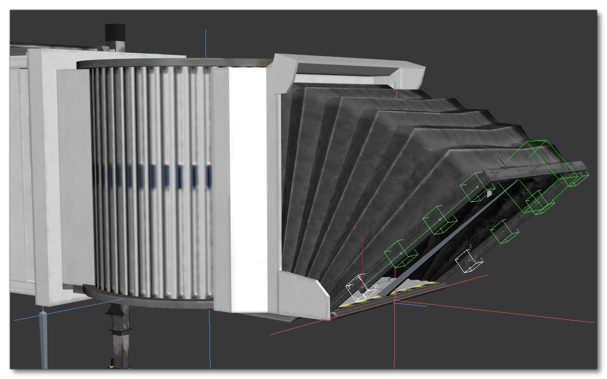
The following image shows the "deployment" animation (which inclines the edges of the hood), for both left and right side:
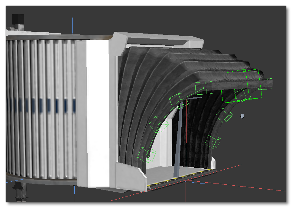
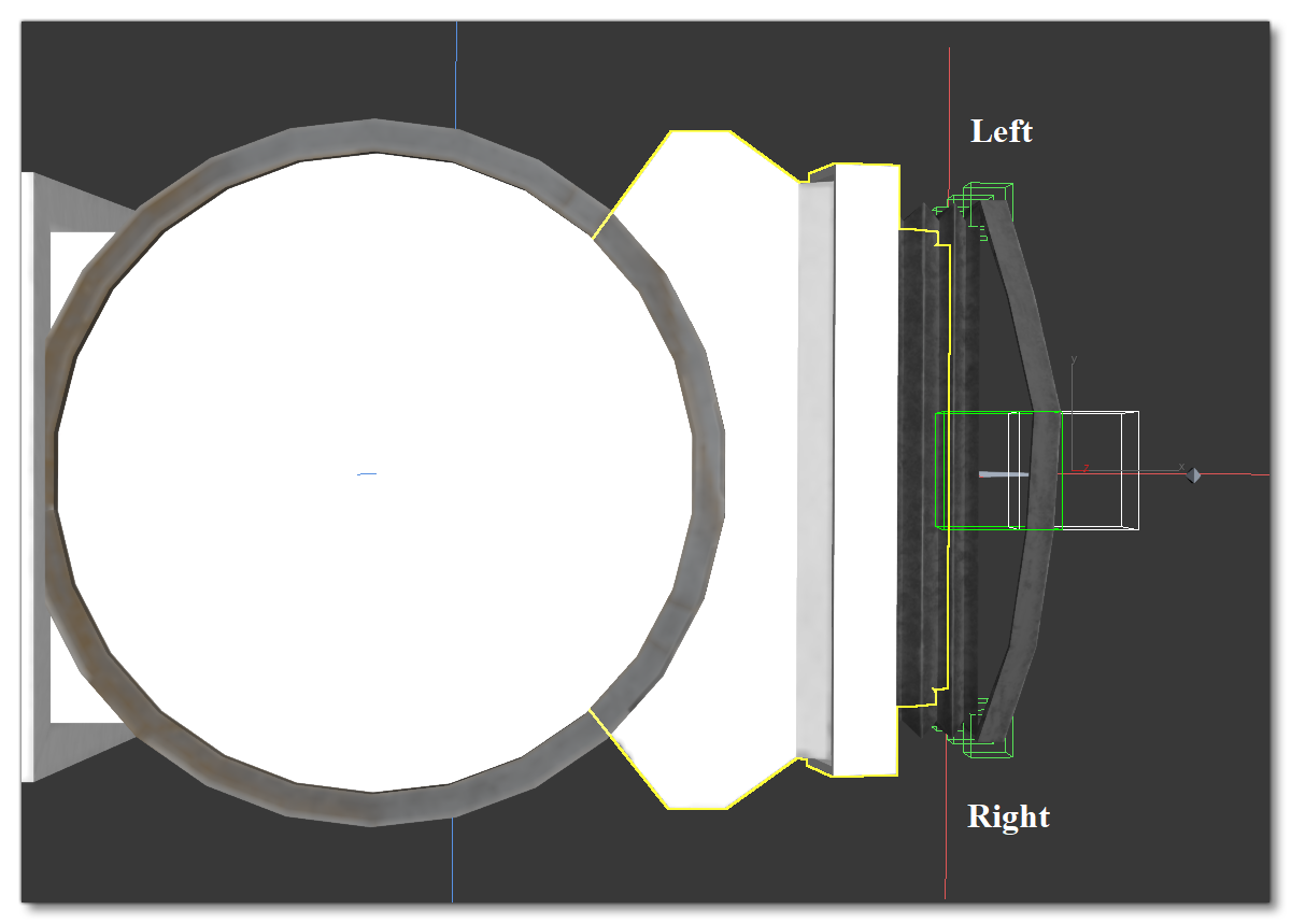
The following image shows the "bend" animation, for both left and right side, here at the last frame of animation.:
The following image shows the "top vertical" animation. Here shown at last frame, but its "default" state should be at the middle of the animation, with the first frame being below the default position: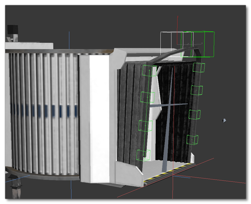
The following image shows the "top horizontal" animation. Here shown at last frame, but its "default" state should be at the middle of the animation, with the first frame being in the back:
Finally, you can see the source of the Microsoft Flight Simulator 2020 base jetway as a reference, available in the Samples\Jetway folder of the SDK.
Configuring The Hood Model Behaviors
In the model behaviors of the jetway (see <Behaviors> for more information), the six animations are defined in six templates used to properly control them. All pre-defined templates are available by using:
<Include Path="Asobo\Misc\SimObjects.xml"/>
Model behavior template ASOBO_Jetway_Hood_Left_Bend uses the SimVar JETWAY_HOOD_LEFT_BEND, and controls the left bending animation by percentage of animation length. Its parameter ANIM_NAME contains the name of the corresponding animation, while PERCENT_PER_SECOND is the speed of the animation.
Model behavior template ASOBO_Jetway_Hood_Left_Deployment uses the SimVar JETWAY_HOOD_LEFT_DEPLOYMENT, and controls the left inclination animation by angle. Its parameter ANIM_NAME contains the name of the corresponding animation, while DEGREE_PER_SECOND is the speed of the animation. Finally, MIN_ANGLE and MAX_ANGLE contain the angles (in degrees) at the start and end of the animation, where 0 is a default vertical position of the hood.
Similarly, the right side of the jetway hood uses Model behavior templates ASOBO_Jetway_Hood_Right_Bend and ASOBO_Jetway_Hood_Right_Deployment, associated with SimVars JETWAY_HOOD_RIGHT_BEND and JETWAY_HOOD_RIGHT_DEPLOYMENT.
Model behavior template ASOBO_Jetway_Hood_Top_Horizontal uses the SimVar JETWAY_HOOD_TOP_HORIZONTAL, and controls the horizontal animation of the top part of the hood, by percentage of the animation length. Its parameter ANIM_NAME contains the name of the corresponding animation, while PERCENT_PER_SECOND is the speed of the animation.
Similarly, the vertical animation of the top of the hood is controlled by ASOBO_Jetway_Hood_Top_Vertical, using JETWAY_HOOD_TOP_VERTICAL, with the same parameters.
Other Jetway SimObject Specifications
Since its base is not moving, a Jetway should be a SimObject of type StaticObject, and thus have an appropriate folder organisation as well as a correct sim.cfg file.
A Jetway also has access to the following specific model behavior templates (usable by including "Asobo.xml") and simvars:
- A template
ASOBO_Jetway_Wheel_Rollcan control an animation that rolls the wheels of the jetway (which should contain one full turn an no more, to be looped properly) by using the SimVarJETWAY_WHEEL_SPEED. Its parameters areANIM_NAME, the name of the animation, andWHEEL_RADIUScontaining the radius (in meters) of the rolling wheel.
- A template
ASOBO_Jetway_Wheel_Orientationhelps control an animation to rotate the wheels when the jetway moves to its side or diagonally. This template uses SimVarJETWAY_WHEEL_ORIENTATION_TARGET, which is approximative, and sets the SimVarJETWAY_WHEEL_ORIENTATION_CURRENTafter some smoothing, using it to control the animation. Preferably, the animation should be covering a 180° interval, for example: -90° to 90°. The elements containANIM_NAME,MIN_ANGLEandMAX_ANGLE(in degrees) where the min should be less than the max,MIN_TO_MAXwhich is1if the animation starts at the min angle, and0otherwise. ParameterSPEEDcontrol the maximum rotation speed (in degrees/second), andSMOOTH_TIME_FACTORis a factor that delays rotation to smooth errors in angles from theTARGETSimVar, which will smooth more and delay more the higher its value is (can be roughly estimated as a delay in seconds).
- Finally,
JETWAY_MOVINGis a boolean SimVar that is true when the jetway is currently moving through IK. It can for example be useful to control sounds of jetway.