THE INPUT PROFILE EDITOR
The Input Profile Editor is used to setup input profiles for a device to use with Microsoft Flight Simulator 2024. The concept here is that you take a device - like a joystick - and then bind the different inputs from the device with specific actions in the simulation, based on various different contexts. You can find out how to use this editor on the following pages:
Overview
The Input Profile Editor can be opened directly from the Editors menu, or - and this is the more common method for opening it - it'll be opened from The Project Editor when you create or edit a profile package. The editor itself looks like this:

At the top of the window you have the various menu items (explained below), and then underneath that you have the Package information, and the Asset Group being edited (which can be changed using the Select... button if you have multiple devices defined in the same package).
You then have the File that is currently being edited as part of the package (this is the Input Configuration XML file), which you can rename using the ✎ button, delete using the 🗑 button, or add a new one using the + button.
Finally you have the information about the device that is being used at the moment to generate the input profile XML. This can be changed by clicking the ✎ button, which will open the Edit Device window:

- Device: This is the device that is being edited, based on the list of devices that are natively supported, and any devices previously defined in the package or other add-ons.
- Product ID: The unique USB ID for the device.
- Composite ID: This is used to identify a device when it is a part of a multi-part device where each part has the same Product ID.
- Hw Version: This is the product hardware version. Some devices can be connected together even if they are from different brands (the value here is usually given by the device itself when plugged in). Note that this is only used by the XBox.
- Device Type: Identifies the type of device based on the input protocols it uses, which can be one of the following:
- Direct Input - A generic stick / device.
- DualSense - A PS5 controller.
- Keyboard - A keyboard.
- Mouse - A mouse.
- XBox Gamepad - An XBox One controller.
- XBox Series Stick - An XBox One compatible joystick.
- XInput - An XInput device.
- XR Controller - Left and right VR/AR controllers.
- Tobii - A Tobii controller.
- Has Buttkicker: The device has Buttkicker haptics incorporated.
Action List
The main part of the Input Profile Editor is taken up with the action list. It is here that you add in the different simulation actions and bind them to one or more inputs. This list can be interacted with in the following two ways:
-
When Show All Actions Is Checked
With Show All Actions checked, every available action in the simulation will be shown. You can then use the filter input box along with the context drop-down list to narrow the available actions down to those you wish to edit.

-
When Show All Actions Is Unchecked
With Show All Actions unchecked, you can click on the Add button at the bottom of the window and then select which action to add for editing from the list. The list can be filtered from the input field at the top to help narrow down this selection.

Once you have actions added into the list, you can then create the primary bindings, and - if you are creating a profile for a specific aircraft - the secondary bindings as well (although generally you will only need to create primary bindings regardless of the target for the profile). To add the bindings you have the following two methods:
- take the input directly from the device by clicking the Get Input button (
 ) and then moving the device joystick or pressing one of the device buttons.
Or:
- use the drop down list button (
 ) and select the input manually.

This process should be repeated for all the different inputs over all the contexts listed in the table above. If you wish to remove an input for an action, then you can click on the eraser ![]() button, and then re-enter the inputs you want to use. If you wish to remove the entire action from the list, then you can use the
button, and then re-enter the inputs you want to use. If you wish to remove the entire action from the list, then you can use the 🗑 button from the Options column.
Action Options
The options column allows you to set up certain properties for the input by clicking the ![]() button, which will open the Action Options window:
button, which will open the Action Options window:

From this window you have different options depending on the different type flags selected:
-
Value Event
By default, a bound input event will send either a 1 or a 0 when pressed/moved/detected. However, it may be that you wish to send a specific value along with the input event, in which case you would set that value here. Note that you must also select MOD_VALUE from the Flags section (explained below) for this option to be visible.
-
Type
This section has a drop down menu where you can check one or more type flags, which will be used to modify and/or override the default input parameters for the input being bound. These type flags are as follows:
- DIGITAL - The input will regarded as being a digital "on/off" input.
- ANALOGICAL - The input will be considered as an analog input. Note that this is supplied for compatibility with certain joystick devices, but usually any analog input would use the AXIS type.
- AXIS - The input will be considered as some kind of analog input.
- MOD_INV - The input will be inverted.
- MOD_UP - Normally input is sent on the press of a button, however when this modifier is added, input will be sent when on the release. This is normally only valid for digital input.
- MOD_PRESSED - When a button is pressed the normal behaviour is for the pressed event to be sent every frame that the button is held down. However when this modifier is added, input will be sent only once, on the initial press. This is normally only valid for digital input.
- MOD_VALUE - The input will send a value other than 0 - 1, as set in the Value Event section. Note that this will only be available when editing Aircraft Specific Input Profiles.
- MOD_AXIS_OVERRIDE - This will be added automatically when you choose the Override Axis option, and signifies that the global axis settings should be overridden by a custom setting for this input event binding. Selecting this option will change the Action Options window to show the current settings for the axis, which can then be expanded and edited (see Override Axis for more information):

- MOD_DELAYED_EXCLUSIVE - This modifier creates a small delay between the press being intercepted and then transmitted. Using this mod means that the input will need to be held down for the event to be triggered.
- MOD_NO_KEYBOARD_LAYOUT - By default, the simulation will auto-convert inputs from ANSI to ISO. For example, if the input is mapped to
Q, then pressingAon an AZERTY keyboard will still activate the mapped event. However, with this modifier, you can disable this default behavior and instead force the input to be "raw" with no conversion.
- MOD_RESET_ONCONTEXT_DISABLED - This modifier will prevent the current value of the input from being reset if the context it belongs to is disabled.
- DIGITAL - The input will regarded as being a digital "on/off" input.
-
Override Axis
This option allows you to set overrides for the various analogue axis response curves on an individual level (ie: changes made here will change axis input response only for the selected axis, overriding the default and Global Override Axis settings). Selecting the option will expand the window to show the different override options:
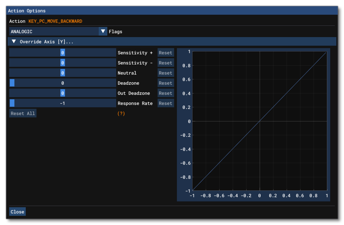
From here you can adjust the following parameters related to the different analog axis:- Sensitivity+ - Changes how sensitive the positive side of the axis is.
- Sensitivity- - Changes how sensitive the negative side of the axis is.
- Neutral - Shifts the neutral zone to the positive or negative side.
- Deadzone - Expands or contracts the deadzone from the central (neutral) position of the device.
- Out Deadzone - Expands a deadzone from the maximal input position of the device.
- Response rate - This will change the amount of temporal smoothing applied to inputs from the device. Set to -1 to disable.
Menus
The top of the Input Profile Editor has a number of menu options, explained below.
File

The following File options exist for the Profile Editor:
-
Save
This option is used to save the input configuration XML file to the package sources.
View

The following view options exist for the Profile Editor:
-
Device Keys
Selecting this option will open the Device Keys window:
 This window shows each of the different "base" controller categories as tabs, and each tab shows the input strings (Key Names) that these devices transmit, along with the numeric value associated with the string. All controllers that can be used by the simulation will fall into one of these categories and use the strings associated with that category. As such, this window is for reference only, primarily for when you need to set up a device without actually having it available or plugged into the machine.
-
Edit ActionDB
Selecting this option will open the ActionDB edit window, where you can edit the contents of the actiondb XML if necessary. In general this should not ever be required, but if you do have to use this, then you should proceed with caution as you can easily break inputs.
NOTE: This option will only work when creating Aircraft Specific Input Profiles.
-
Undo History
This option will bring up the Undo History window:
 This window shows the full list of actions that have been performed since the main Profile window has been opened. You can click on any one of them to go back or forward between the different undo/redo states.
Options

The following additional options exist for the controller setup and will affect how the different inputs will be handled:
-
Split Axis
This option will tell the simulation to differentiate between the +/- inputs on the X / Y / or Z axis. For example, when not checked, the simulation will interpret a joystick stick left and right as simply "Joystick LAXIS X" input. However, when checked, this will now be interpreted as "Joystick LAXIS X-" for moving the joystick left, and "Joystick LAXIS X+" for moving the joystick right.
-
Split POV / Hatswitch
This option will tell the simulation to differentiate the movement of POV hat-switches. For example, when not checked, the simulation will interpret all POV movement (left, up, etc...) as simply "Joystick POV" input. However, when checked, this will now be split based on direction such that left is now "Joystick POV Left", up is "Joystick POV Up", etc...
-
Global Override Axis
This option allows you to set overrides for the various analogue axis response curves on a global level (ie: changes made here will change axis input response for all actions using that input). Selecting the option will open a small window asking you to select the axis to override:

After making a selection the following window will open:

From this window you can adjust the following parameters related to the different analog axis:- Sensitivity+ - Changes how sensitive the positive side of the axis is.
- Sensitivity- - Changes how sensitive the negative side of the axis is.
- Neutral - Shifts the neutral zone to the positive or negative side.
- Deadzone - Expands or contracts the deadzone from the central (neutral) position of the device.
- Out Deadzone - Expands a deadzone from the maximal input position of the device.
- Response rate - This will change the amount of temporal smoothing applied to inputs from the device. Set to -1 to disable.
Related Topics