DEBUG WEATHER SIM

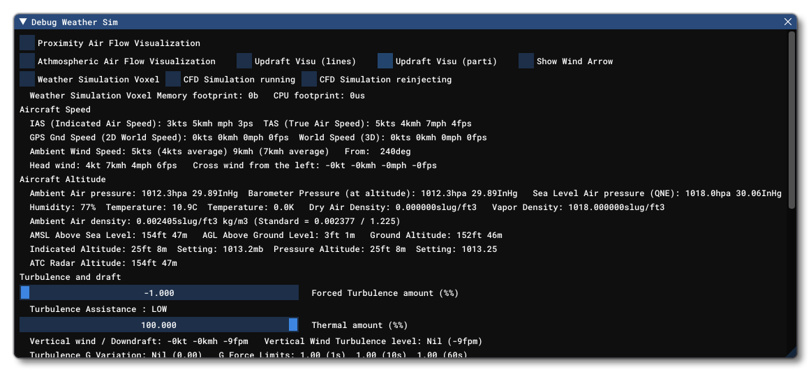
This window is used to debug the and visualise some of the weather effects, in particular those related to airflow and wind, which is useful for debugging gliders. The window shows multiple values related to the weather/airflow and also has the following options:
-
Proximity Air Flow Visualisation
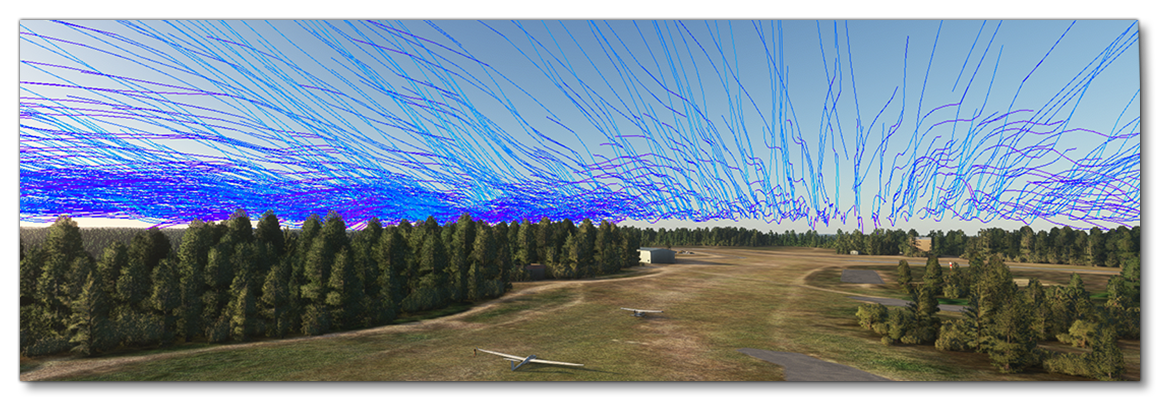
When this option is checked, the simulation will show lines displaying the air flow in close proximity to the ground:

-
Atmospheric Air Flow Visualisation
When this is checked, the simulation will display lines to show the movement of the air flow simulation in the air:NOTE: Selecting this option will also enable the Weather Simulation Voxel option, since the airflow requires the voxel space to be enabled for it to be visualised. If you also check the Proximity Air Flow Visualisation option, then both the proximity and the atmospheric airflow will be animated:

-
Updraft Visualisation (Lines)
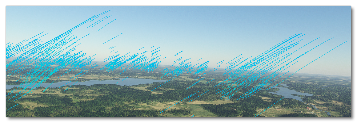
Checking this option will show the areas where the weather simulation is generating updrafts. These areas will be shown using static lines:
NOTE: Selecting this option will also enable the Weather Simulation Voxel option, since the airflow requires the voxel space to be enabled for it to be visualised.
-
Updraft Visualisation (Particles)
Checking this option will show the areas where the weather simulation is generating updrafts. These areas will be shown using dynamic particles:NOTE: Selecting this option will also enable the Weather Simulation Voxel option, since the airflow requires the voxel space to be enabled for it to be visualised.
-
Show Wind Arrow
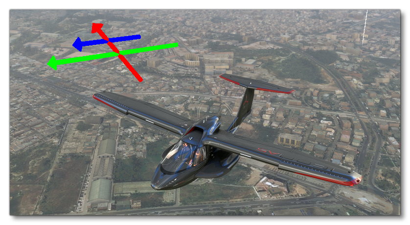
When this option is checked, the simulation will render three arrows above the aircraft:

- Green Arrow: The general wind direction, where the longer the arrow, the more forceful the wind is blowing.
- Blue Arrow: The direction of any wind gusts.
- Red Arrow: The direction of the updrafts that the aircraft is currently passing through.
-
Weather Simulation Voxel
This option shows when the weather simulation voxel is active and being used to generate realistic weather/airflow. This option will be enabled/disabled automatically when you check any of the options that depend on the weather simulation voxel for their visualisation, and as such you cannot enable/disable it manually.
-
CFD Simulation Running
Checking this option will enable the CFD simulation. You can find out more about this from the How It Works section of the Aircraft Debug documentation.
NOTE: Selecting this option will also enable the Weather Simulation Voxel option, since the CFD requires the voxel space to be enabled.
-
CFD Simulation Reinjecting
When checked, this option will affect the interaction (collision calculation) between the fluid simulation and the rigid body aircraft simulation (note that if the aircraftflight model CFGfile has theCFD_ReinjectBodyparameter set to 1 (TRUE) then this option will already be checked and cannot be unchecked). In theory the force applied on the fluid by the airframe is always exactly opposite from the force applied on the airframe by the fluid.
-
Forced Turbulence Amount %
This slider can be used to force the amount of turbulence within the weather system. Activating the Atmospheric Air Flow Visualisation option will permit you to view what effect this will have. Note that the effects of changing this slider may take a few moments to become visible/active in the simulation.
-
Thermal Amount %
This slider can be used to set the amount of thermals available in the zone. Activating the Updraft Visualisation (Lines) option will permit you to view what effect this will have. Note that the effects of changing this slider may take a few moments to become visible/active in the simulation.
Related Topics