ELECTRICAL SYSTEM DEBUG

The Electrical System debug windows are opened from the Debug menu of the Behaviors Debug window or from the SimObject Debug Menu itself. From this window you can get an overview of the components that make up the Modular Electrical System, as well as debug and edit them.
This debug view uses two windows, where the main window shows detailed information and options for the components of the electrical system, and the "quick access" window shows a customisable overview of the components. The idea here is to facilitate the comparisons between components, for example you can have a supplier open in the main window, editing it's values, while checking the input of a relevant consumer in the quick access window.
Note that in addition to this debug window, there will be messages logged in the Console which will signal problems, warnings, and changes as they are detected by the simulation. The console can be filtered using the Message group filter to show only the electrical system output, making it easier to find the corresponding messages:

NOTE: The console shows you messages related to all electrical systems currently active, which is something to be aware of when checking things.
The Electrical System Debug Window
The main electrical system debug window has an Options menu at the top with the following:

- Breakers Trip: When this option is checked, breakers will trip when overloaded, and when it is unchecked they will not.
- Infinite Batteries: When this option is checked, batteries will never deplete as each system update they will be set to 100% capacity.
The rest of the main window is taken up with tabs showing different information related to the electrical system. Each of these tabs is explained below.
Instance

On this tab you will find all the different component instances that make up the electric system of the aircraft. This list can be filtered using the textbox at the top, and the filter can be removed using the Clear button. Clicking on any of the instances in the list will show additional information and options in the section to the right. These are as follows:
-
Batteries
Each instance of the Battery components shown in the instances list will show the following additional information when selected:-
Battery Tester

In this section you can create a "fake" battery profile and test out the different battery types, capacities, and voltages, then see what effect they will have on the discharge curve (the changes made here will have no impact on the simulation and are simply meant for testing setup values). Note that you can click and drag the Battery Current Capacity to see the Low / High / Current values at different capacities, and if you click on the graph legend colour boxes you can show/hide the given curve.
-
Consumers Powered By This Supplier

This section will show the different consumers that the component is powering. Each component group can be expanded to show a table of individual components that are connected to the supplier, along with different values associated with it. Note that - by default - not all of the table properties shown in the image above will be visible, but you can right-click on the table headers and enable / disable those that you need / don't need. Also note that the Line State entry is a toggle and clicking it will disconnect the component from the line, and that some list values can be edited in real-time to help debug the system.
-
ON / OFF
The ON / OFF section simply shows you the current state of the battery, and has a button (
Turn ON/Turn OFF) that can be used to toggle this state. Note that this may only work for a single frame before being reset, depending on the behavior setup. -

The line section shows the name of the line, and clicking on this will expand the section to show the Endpoint A and Endpoint B entries. These are the two components that the line connects to, and each can be expanded to show the full properties for the component. The properties shown, are the exact same as those shown when the component is selected from the list in the main debug window. You also have a button -
Disconnect- which can be used to disconnect the current component from the line. -
Consumer Runtime Values

This section details the currently simulated Load, Tension and Power Supplied to the consumer component.
-
Supplier Runtime Values

This section details the currently simulated Voltage, Load and Power of the supplier component.
-
Battery Runtime Values

In this section you have the actual values for the battery as it is being used in the simulation. These values will update over time as the simulation runs, and there are no editable fields. However you can force discharge or force charge the battery using the
Refill BatteryandEmpty Batterybuttons, and see the effect on the discharge curve and output values. -
Battery Config Values

Here you have a number of sections related to how the battery is configured. Only those that are relevant to the battery type will be highlighted. These sections can also be expanded to show the configuration value (in yellow) and the cached value (in white). The cached value is the value that is set in the CFG file and will often match the configuration value, but the configuration value can be changed, for example, using a SimVar or an FLT file.
-
-
Generators
Each instance of the Generator components shown in the instances list will show the following additional information when selected:
-
Consumers Powered By This Supplier
Here you can find the list of consumers that this component is powering. See Consumers Powered By This Supplier for more information.
-
ON / OFF
The ON / OFF section simply shows you the current state of the generator, and has a button (
Turn ON/Turn OFF) that can be used to toggle this state. Note that this may only work for a single frame before being reset, depending on the behavior setup. -
Line
This shows the name of the line that the component is connected to. See Line for more information.
-
Runtime Values
 Here you can find the values that are used in the simulation for the generator. These are the Frequency, the Vʳᵐˢ, the Load and the Power of the generator, and they will change in real-time based on the current state of the simulation.
 -
Config Values
 Here you have a number of sections related to how the generator is configured. Only those parameters that are fully configured in the CFG file will be highlighted. These can be expanded to show the configuration value (in yellow) and the cached value (in white). The cached value is the value that is set in the CFG file and will often match the configuration value, but the configuration value can be changed, for example, using a SimVar or an FLT file.
-
-
External Power Units
Each instance of the External Power components shown in the instances list will show the following additional information when selected:
-
Consumers Powered By This Supplier
Here you can find the list of consumers that this component is powering. See Consumers Powered By This Supplier for more information.
-
ON / OFF
The ON / OFF section simply shows you the current state of the external power unit, and has a button (
Turn ON/Turn OFF) that can be used to toggle this state. Note that this may only work for a single frame before being reset, depending on the behavior setup. -
Line
This shows the name of the line that the component is connected to. See Line for more information.
-
Runtime Values
 Here you can find the values that are used in the simulation for the generator. These are the Frequency, the Voltage, the Load and the Power of the generator, and they will change in real-time based on the current state of the simulation. Note that you also have a checkbox which you can click to make the GPU available (however this will depend on the situation of the aircraft in the simulation - if you are in flight, for example, this will not be possible).
 -
Config Values
 Here you have a number of sections related to how the ground power unit is configured. Only those parameters that are fully configured in the CFG file will be highlighted. Many of these sections can be expanded to show the configuration value (in yellow) and the cached value (in white). The cached value is the value that is set in the CFG file and will often match the configuration value, but the configuration value can be changed, for example, using a SimVar or an FLT file.
-
-
Circuits
Each instance of the Circuit components shown in the instances list will show the following additional information when selected:
-
Suppliers Powering This Consumer

Here you can find a list of the power suppliers that are giving power to the component. The suppliers are shown as a table of components and all the different values associated with them. Note that - by default - not all of the table properties shown in the image above will be visible, but you can right-click on the table headers and enable / disable those that you need / don't need. Also note that the Line State entry is a toggle and clicking it will disconnect the component from the line.
-
ON / OFF
The ON / OFF section simply shows you the current state of the external power unit, and has a button (
Turn ON/Turn OFF) that can be used to toggle this state. Note that this may only work for a single frame before being reset, depending on the behavior setup. -
Can Function
This section simply shows whether the circuit can function or not (ie: if it is powered or not).
-
Type
This shows the type of circuit that is being viewed.
-
Line
This shows the name of the line that the component is connected to. See Line for more information.
-
Runtime Values
 Here you can find the values that are used in the simulation for the circuit. These are the Load, the Tension, the Power Supplied, the Resistance, and the Power setting of the circuit. These values will change in real-time based on the current state of the simulation. Note that you also have a slider beside the power setting, which you cab click and drag to change the percentage power being supplied to the circuit.
 -
Config Values
 Here you have a number of sections related to how the circuit is configured. Only those parameters that are fully configured in the CFG file will be highlighted. Many of these sections can be expanded to show the configuration value (in yellow) and the cached value (in white). The cached value is the value that is set in the CFG file and will often match the configuration value, but the configuration value can be changed, for example, using a SimVar or an FLT file.
-
-
Buses
Each instance of the Bus components shown in the instances list will show the following additional information when selected:
-
Runtime Values
 Here you can find the values that are used in the simulation for the bus. These are the Bus Voltage, the Bus Load, and the Bus Power settings, and these values will change in real-time based on the current state of the simulation.
 -
Connections
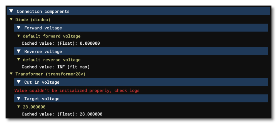
 This section lists all the various connections to the bus being viewed. You can expand each connection and see a button to
 ConnectorDisconnectthe connection, as well as two further expandable regions that show the Endpoint A and Endpoint B for the bus. Endpoint A is the bus component itself, while Endpoint B is the component that the bus connects to, and each can be expanded to show the full properties for the component. The properties shown, are the exact same as those shown when the component is selected from the list in the main debug window. Some connections will have an additional Connection Components section, which lists the Transformers and Diodes connected to the bus:
 Only those parameters that are fully configured in the CFG file will be highlighted. Many of these sections can be expanded to show the configuration value (in yellow) and the cached value (in white). The cached value is the value that is set in the CFG file and will often match the configuration value, but the configuration value can be changed, for example, using a SimVar or an FLT file.
-
Lines

On this tab you will find all the different Lines defined for the aircraft electrical system. This list can be filtered using the textbox at the top, and the filter can be removed using the Clear button. The line instances are shown in a table which has the following fields:
- Name - This is the name of the line.
- ID - This is the ID of the line, which is the component type plus its index number from the CFG file.
- State - This is the line state, either connected or disconnected. You can click this item and it will toggle the line between the two states.
- Connection Components - Here you can see the different possible connection components - Breaker, Transformer, or Diode. If the component is white then it has been defined for the line, and you can mouse over it to get more information about it.
Clicking on any of the line instances in the list will show additional information and options in the section to the right:

Here you find the same Connect / Disconnect toggle for the line as well as the two Endpoints (A and B). These endpoints can be expanded to show information about each of the endpoint components, along with (depending on the component) additional connections.
Breakers

On this tab you will find all the different Breakers defined for the aircraft electrical system. This list can be filtered using the textbox at the top, and the filter can be removed using the Clear button. The breaker instances are shown in a table which has the following fields:
- Breaker - This is the name of the breaker.
- Line - This is the name of the line the breaker is on.
- Load / Rated Current - Here you can find the current load and the rated current for the breaker.
- Trip Time - If the breaker has been tripped, then this will show how long it has been tripping for, and if you hover over the value, a tooltip will also show how long it took the breaker to trip.
- State - This is the breaker state, either pushed or pulled. You can click this item and it will toggle the breaker between the two states.
Clicking on any of the breaker instances in the list will show additional information and options in the section to the right:

The top of this section has the following global options:
- Push All Breakers - Pushes all the breakers defined in the electric system.
- Pull All Breakers - Pulls all the breakers defined in the electric system.
- Breakers Trip - This can be set to either DEACTIVATE or ACTIVATE. When deactivated breakers cannot be tripped, and when activated, they can (this is the same as the Breakers Trip option in the Options menu).
Constants

This tab is very similar to the Instance tab, in that it shows a list of electrical system components, and you can click on them to inspect their setup in the right half of the view. The table list itself can be filtered using the textbox at the top, and the filter can be removed using the Clear button, and it shows simply the Name of the component and it's ID (the component type plus its index number). The main difference between this tab and the Instance tab is that here you can also find things that are "data only" elements, for example, consumer and supplier definitions.

Logs

The Logs tab is simply a log of events related to the electrics system. This differs from the Console output as it will only log information related to the system of the current SimObject, and not all SimObjects present in the scene. The checkboxes at the top can be used to filter out the different levels of log information, Info, Warnings, and Errors.
The Quick Access Window

This window offers a quick view of all the electrical system components. In this window, all the components are listed in tables and you can click on any of the components to open them in the main debug window. You can also filter the components shown in the tables using the textbox at the top, and the filter can be removed using the Clear button. Note that in all the tables, you can right-click on any column header to select what information is shown / hidden.
Suppliers
 The Supplier section shows all the suppliers defined in the aircraft. The top of the section has buttons to
 Turn All On and Turn All Off, and there is a slider that can be clicked on and then dragged to force the battery capacity to a specific value (this will only be maintained for as long as you hold the mouse-button down). The table has the following columns (not all are visible by default):
- Name - The name of the supplier as defined in the CFG file.
- State - Whether the supplier is On or Off. You can click on this entry and toggle the supplier between the two states.
- Line State - The current state of the supplier's line, either Connected or Disconnected. You can click on this entry and toggle the supplier between the two states.
- Load - The current load in Amps.
- Average Load - The average load in Amps.
- Tension - The tension in Volts.
- Average Tension - The average tension in Volts.
- Power - The power in Watts
- Capacity - The current supplier capacity (batteries only). This is a slider and you can click and drag on it to change the capacity in real-time.
- Consumers - This is the number of consumers that are using the supplier.
Circuits
 The Circuit section shows all the circuits defined in the aircraft. The top of the section has buttons to
 Turn All On and Turn All Off, and there is selection menu for selecting the circuit type. The table has the following columns (not all are visible by default):
- Name - The name of the circuit as defined in the CFG file.
- State - Whether the circuit is On or Off. You can click on this entry and toggle the circuit between the two states.
- Can Function - Whether the circuit is can function (YES) or not (OFF).
- Line State - The current state of the circuit's line, either Connected or Disconnected. You can click on this entry and toggle the circuit between the two states.
- Power Setting - The power currently being supplied to the circuit. This is a slider and you can click and drag on it to change the power in real-time.
- Load - The load in Amps.
- Tension - The tension in Volts.
- Power - The power in Watts
- Suppliers - This is the number of suppliers that are on the circuit.
Buses
 The Bus section shows all the buses defined in the aircraft. This table has the following columns (not all may be visible by default):
- Name - The name of the bus as defined in the CFG file.
- Load - The current load in Amps.
- Tension - The tension in Volts.
- Power - The power in Watts.
Lines
 The Line section shows all the lines defined in the aircraft. The top of the section has buttons to
 Connect All and Disconnect All, and the table below has the following columns:
- Name - The name of the line as defined in the CFG file.
- State - Whether the line is Connected or Disconnected. You can click on this entry and toggle the line between the two states.
Breakers
 The Breaker section shows all the breakers defined in the aircraft. The top of the section has buttons to Push All and Pull All, and the table below has the following columns (not all are visible by default):
- Name - The name of the breaker as defined in the CFG file.
- State - Whether the breaker is Pushed or Pulled. You can click on this entry and toggle the breaker between the two states.
- Line State - The current state of the supplier's line, either Connected or Disconnected. You can click on this entry and toggle the supplier between the two states.
- Load / Rated Current - The current load and the rated current, in Amps.
- Trip Time - If the breaker has been tripped, then this will show how long it has been tripping for, and if you hover over the value, a tooltip will also show how long it took the breaker to trip.
Related Topics