PROPELLERS, TURBINES AND BLADES
This page outlines how to model and texture propellers, turbine fans or rotor blades. The principle for Microsoft Flight Simulator 2024 is different to that of previous versions in that you only need to make a single version of the object as there is no longer any need to create "stopped", "slow" and "blurred" versions, since all blurring is handled by the simulation. Note that you can include a lower quality version of the object, but this is optional and explained further down this page in the Low Detail Model section.
Modeling And Texturing
The modelling and texturing process is exactly the same for rotors, turbine fans and propellers, and requires that you follow these rules:
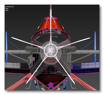
- The whole propeller / turbine fan / rotor - including blades, cone or any other rotating element - must be made with one single node and use one single material.
- In the case where the blade pitch can be altered, you should make the object a skinned mesh. See the section on Propeller Pitch, below.
- Rotational blur will be generated in the simulation using a shader which simulates rotation along the Z-axis of the object (this is the Y-axis in 3ds Max). Therefor, any included animation is ignored and no additional art for blur is required. This also means that you do not need to animate things like the cone rotation on a propeller.
- Additionally, for turbine fans, it should be noted that the fan node Z-axis direction determines the direction of rotation when the in-simulation shader is applied to them. If the Z-axis is towards the back of the aircraft, then the turbine fans will rotate anti-clockwise, and if it's towards the front of the aircraft, it will rotate clockwise.
- Each LOD of the aircraft being designed must include the propeller model.
- If propeller / turbine fan / rotor root bone is at the top of its own hierarchy, then you cannot export as a sub-model.
- The propeller / turbine fan / rotor must only use one material of the type Propeller.
- The propeller material requires the albedo (Base Color) texture, and you should also supply Occlusion(R) Roughness(G) Metallic(B) and Normal textures.
- All textures used in the material must be opaque and have a vertex alpha of 1.0. Note that using the "opaque" setting in the material will not work for this, the texture itself has to be opaque. When designing the textures for a propeller, keep in mind that the back should always be dark to avoid dazzling the pilot.
The image below illustrates a correctly modeled propeller with a single material:

Propeller Pitch
For a propeller to correctly show blade pitch changes it needs to be a skinned mesh, and once the mesh is skinned:
- Add helpers for the pitch of each of the propeller blades.
- Frame 0 should correspond to the maximum attack angle, when the blade is perpendicular to the nose:
- You should then animate all the blades to rotate 360° (as shown in the image below).
- Since the propeller is now skinned using helpers, when the blade helper rotates, the skinned part of the mesh impacted by it will rotate as well.
- Ensure that the helpers are plugged into an animation group on export.
- Setup the model behaviour XML to connect the animation with the simulation (explained here: File Setup - XML)
Shadow Flickering
One potential issue that may occur when creating rotor blades or propellers is that the shadow it casts may "flicker" and look wrong when they are in movement. To prevent this issue you will need to follow these steps:
- Ensure that the Don't Cast Shadows option is checked in the propeller / rotor material.
- Duplicate the propeller cone / rotor mast which will serve as the shadow occluder.
- Next, duplicate the original material, assign it to the duplicated cone / mast, then change it's material type from Propeller to Standard and make sure the Don't Cast Shadows option is not checked.
- Make this a child of the optimized blurred version of the propeller so that it appears/disappears at the same time.
- Finally, push the vertices a bit inward so as to keep the rotating blurred version visually on top at all time.
Low Detail Model
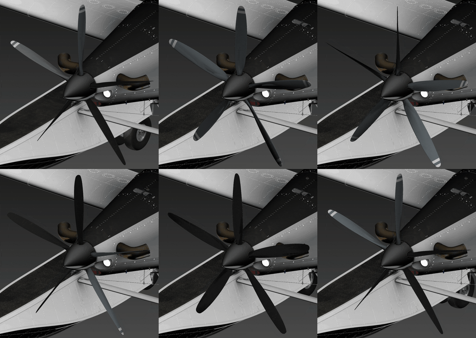
When creating your propellers and rotors (but not turbine fans, as they will always use the same model) there is the option of adding in a "low detail" version of the model. This option exists due to the way that the blur system works, which is to draw N additional times the object mesh and apply a shader. This means that the polycount for the propeller / rotor will be multiplied N times as well. For something like a simple propeller, this is not usually an issue, but if you are applying this blur technique to something like a turbo fan on all 4 engines of a passenger jet, then all of a sudden, there can be 100,000+ triangles x N (and depending on the rotation speed, N can go easily to 15). This would translate into 1,500,000 triangles just for the blur effect, which could obviously cause performance issues.
To mitigate this potential issue, we recommend that you create an additional low poly model of the propeller / rotor, positioned at the exact same place the high quality version is. It should follow the same guidelines listed at the top of this page, only have a much reduced triangle count, and the object node should be unique so it can be referenced in the CFG files and the model XML. The simulation will switch between models based on the RPM of the object at any given time. The image below shows a high-quality version of a propeller beside the low quality version for reference (mouse over the image to see the wire-frames):


Helicopter Blades
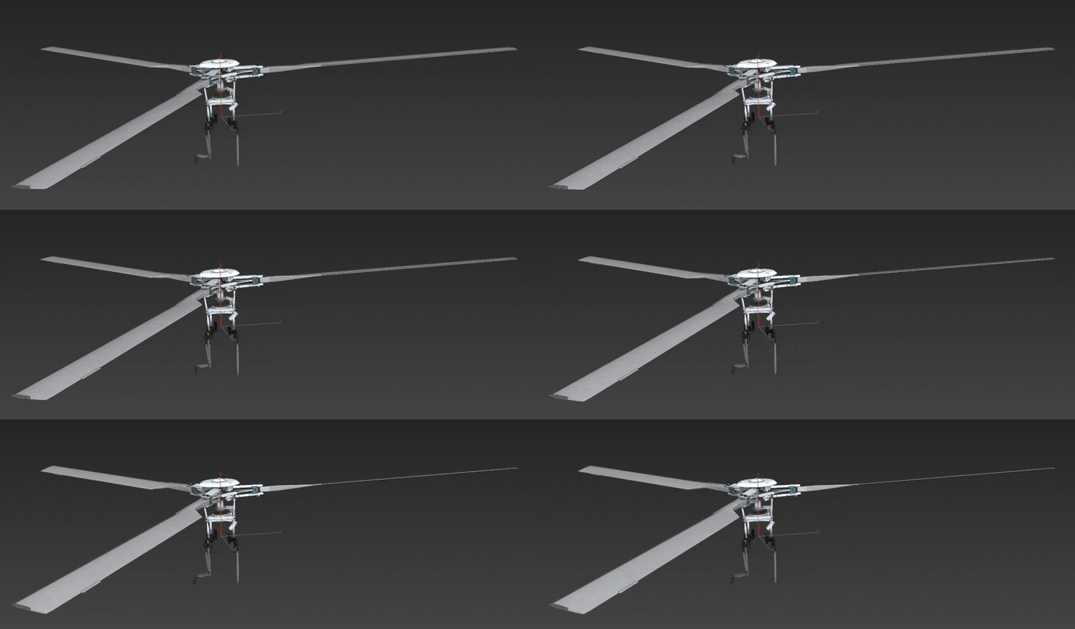
The principles for creating helicopter blades are the same as those outlined above for propellers, however they will also require one additional step which that they need to be skinned so that they adequately show blade flex and piston/swashplate animations. Therefor the entire rotor setup needs to be a single skinned mesh, with the correct hierarchy: you should have a root node which contains the propeller mesh and its skin nodes.
Blade Setup
For helicopters, three blade positions are needed:
- Straight - This one is simply the neutral blade position, essentially the base model before skinning.
- Down - This is the stationary position and is probably the most important as it represents the blade position when the engine is off and when the covers are on when doing the preflight checks. In this position the blade socks should be aligned coherently with the blades and skinned to the blade mesh (see Covers, Chocks, And Pins for more information). This position should be the first frame of the animation.
- Up - This position is used when the helicopter is at high RPM, and it should be the last frame of the animation.
Once you have set up the skinned mesh and animation, you will also need to setup the model behaviour XML to be able to automatically change the blade flex amount based on the state of the simulation. This is explained in the File Setup - XML section, below.

Rotor Mast Setup
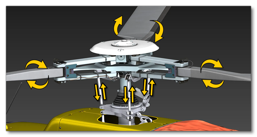
Rotor mast and blades constitute the main propeller mesh for helicopters, and the the rotor mast is connected to the engine via two swashplates and their corresponding pistons. These pistons and the rotors should all use the same Propeller material and be animated so that the pistons drive the blade angle, as illustrated below:
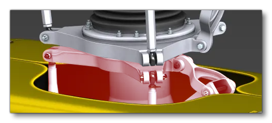
Note that because everything has to be skinned together to work, everything that is connected to the rotor has to be exported together and in the same hierarchy. This means the lower engine swashplate and its pistons (highlighted in red, below) will use the Standard material but still be exported with the propeller for everything to work.
For blade feathering, the animation should be set up as follows:
- First Frame: This is the feather minimum, where the blade are parallel to the ground.
- Last Frame: This is the maximum angle of the blades.
You will also need to setup the model behaviour XML to be able to automatically change the feathering amount based on inputs from the simulation. This is explained in the File Setup - XML section, below.
Tail Rotor
When it comes to the tail rotor, everything explained in the sections above is applicable although obviously the animation and model is simplified. This section of the helicopter will also need to be exported with its own hierarchy and as its own part.

For the tail feather animation you will need the following frames:
- Frame 0: Blades pitched such that the rotorcraft would turn left.
- Frame 1: Blades at a neutral pitch such that the rotorcraft would fly straight.
- Frame 2: Blades pitched such that the rotorcraft would turn right.
You will also need to setup the model behaviour XML to be able to automatically change the feathering amount based on inputs from the simulation. This is explained in the File Setup - XML section, below.

File Setup - CFG
Once the aircraft has been modeled, there are a few specific parameters that need to be defined so that the blurring will be applied correctly in the simulation. The actual parameters you need to edit will depend on the type of engine the aircraft uses, but the setup of each is explained below.
Propellers
For Propellers, the engines.cfg will need to be configured correctly, specifically the prop_node.n parameter in the [PROPELLER] section. Here there should be a list of nodes for each propeller following the order of the engines, for example, prop_node.0 will match with engine.0 (as defined in the [GENERALENGINEDATA] section). The example settings below are for a twin engine turbo-prop aircraft:
prop_node.0 = NODES:prop_L
prop_node.1 = NODES:prop_R
It is also possible to configure more than one node per engine, such that you have 2 versions of a propeller with low or high detail, for example:
prop_node.0 = NODES:prop_L, prop_L_lowdetail
prop_node.1 = NODES:prop_R, prop_R_lowdetail
For more information please see the Low Detail Model section, below, and be aware that when you supply two nodes for low and high polygon versions, you will also need to adjust the model behaviour XML (as explained in the File Setup - XML section).
Turbine Fans
For turbine engines with turbine fans, the engines.cfg will need to be configured correctly, specifically the turbine_node.n parameter in the [TURBINEENGINEDATA] section. Here there should be a list of nodes for each turbine following the order of the engines, for example, turbine_node.0 will match with engine.0 (as defined in the [GENERALENGINEDATA] section). Additionally, you will need to add the turbine_blades parameter to set the number of blades inside the turbine. There is also the option to use the N1_100pc_rpm parameter. By default the speed at which the turbine fan will spin is based on the engine RPM however for turbines you will typically want to use the N1 RPM to give a more realistic blurring in tune with the engine power. This value is not calculated automatically by the simulation and so you will have to provide the value in the N1_100pc_rpm to indicate the RPM at 100% of N1 if you want this level of realism.
The example settings below are for a twin engine turbo fan aircraft:
N1_100pc_rpm = 4397
turbine_blades = 18
turbine_node.0 = Nodes:turb_L
turbine_node.1 = Nodes:turb_R
It is also possible to configure more than one node per engine, such that you have 2 versions of a turbine fan with low or high detail, for example:
turbine_node.0 = Nodes:turb_L, turb_L_lowdetail
turbine_node.1 = Nodes:turb_R, turb_R_lowdetail
For more information please see the Low Detail Model section, below.
Rotor Blades
For rotors, the flight_model.cfg will need to be configured correctly, specifically the rotor_node.n parameter in the [HELICOPTER] section. Here there should be a list of nodes for each rotor, numbered from 0. The example settings below are for a helicopter with a main rotor and a tail rotor:
rotor_node.0 = Nodes:rotor_main
rotor_node.1 = Nodes:rotor_tail
It is also possible to configure more than one node per rotor, such that you have 2 versions of the rotor blade model with low or high detail, for example:
rotor_node.0 = Nodes:rotor_main, rotor_main_lowdetail
rotor_node.1 = Nodes:rotor_tail, rotor_tail_lowdetail
For more information please see the Low Detail Model section, below.
Note On Modular Aircraft
The default way to make an aircraft in Microsoft Flight Simulator 2024, is to make a Modular Aircraft SimObject. This means that the propeller / turbine fan / rotor may not be a part of the Common folder, and instead need to be "attached" through the use of Presets. For example, your common folder may simply be the fuselage, and then the wings, engines, landing gear, etc... are all attached when the aircraft is loaded into the simulation based on the chosen preset. In these cases, the node parameters given above can all be given a SimAttachmentAlias to identify the part they should be associated with in the preset. For example:
prop_node.0 = SimAttachmentAlias:Exterior #Nodes:prop
turbine_node.0 = SimAttachmentAlias:Wing_L #Nodes:turbine_L
rotor_node.0 = SimAttachmentAlias:WheelHub #Nodes:rotor_main
The alias used in these parameters is defined in the attached_objects.cfg (in the alias parameter) for the Presets that require the propeller / turbine fan / rotor. If the node(s) for the propeller / turbine fan / rotor are found in the common folder then this alias is not required in the node definition.
File Setup - XML
In addition to some setup required in the CFG files (as explained above), you will also need to add some XML into the Model XML for the aircraft part that has the propellers or rotors. In most cases this XML will require the use of one of the included Default Templates.
Propeller XML
For propellers to use the low detail mesh correctly, you will need to use the ASOBO_ET_ENGINE_Propeller_Model_Swap_RPM_Template in the model XML file, something like this:
<Include ModelBehaviorFile="Asobo_EX1\Index.xml" />
<Include ModelBehaviorFile="Asobo_EX1\DefaultConfig.xml" />
<Include ModelBehaviorFile="ASOBO_EX1\ExteriorDefs.xml"/>
...
...
<Component ID="PROPELLER_VISIBILITY">
    <UseTemplate Name="ASOBO_ET_ENGINE_Propeller_Model_Swap_RPM_Template">
         <NODE_VISIBLE_AT_HIGH_RPM>low_quality_node_name_here</NODE_VISIBLE_AT_HIGH_RPM>
         <NODE_VISIBLE_AT_LOW_RPM>high_quality_node_name_here</NODE_VISIBLE_AT_LOW_RPM>
    </UseTemplate>
</Component>
For propellers that have blade pitch controls you would need the ASOBO_GT_Anim_Template, which would be setup something like this:
<Include ModelBehaviorFile="Asobo_EX1\Index.xml" />
<Include ModelBehaviorFile="Asobo_EX1\DefaultConfig.xml" />
<Include ModelBehaviorFile="ASOBO_EX1\ExteriorDefs.xml"/>
...
...
<Component ID="PROPELLER_BETA">
    <UseTemplate Name="ASOBO_GT_Anim_Template">
        <ANIM_NAME>PROPELLER_PITCH</ANIM_NAME>
        <ANIM_CODE>90 (A:PROP BETA:1, degrees) - dnor</ANIM_CODE>
        <ANIM_LENGTH>360</ANIM_LENGTH>
        <ANIM_LAG>100</ANIM_LAG>
        <ANIM_WRAP>True</ANIM_WRAP>
    </UseTemplate>
</Component>
Rotor XML
For rotors to use the low detail mesh correctly the XML should have the ASOBO_ET_ENGINE_Rotor_Model_Swap_RPM_Template, and look like this:
<Include ModelBehaviorFile="Asobo_EX1\Index.xml" />
<Include ModelBehaviorFile="Asobo_EX1\DefaultConfig.xml" />
<Include ModelBehaviorFile="ASOBO_EX1\ExteriorDefs.xml"/>
...
...
<Component ID="ROTOR_VISIBILITY">
    <UseTemplate Name="ASOBO_ET_ENGINE_Rotor_Model_Swap_RPM_Template">
         <NODE_VISIBLE_AT_HIGH_RPM>low_quality_node_name_here</NODE_VISIBLE_AT_HIGH_RPM>
         <NODE_VISIBLE_AT_LOW_RPM>high_quality_node_name_here</NODE_VISIBLE_AT_LOW_RPM>
    </UseTemplate>
</Component>
For rotors to properly have the coning effect you'll need the ASOBO_GT_Anim_Template template and the ASOBO_Get_Rotor_Coning_Animation_Parameters parameter function. The XML will be something like this:
<Include ModelBehaviorFile="Asobo_EX1\Index.xml" />
<Include ModelBehaviorFile="Asobo_EX1\DefaultConfig.xml" />
<Include ModelBehaviorFile="ASOBO_EX1\ExteriorDefs.xml"/>
...
...
<Component ID="ROTOR_CONING">
    <UseTemplate Name="ASOBO_GT_Anim_Template">
        <UseParametersFn Name="ASOBO_Get_Rotor_Coning_Animation_Parameters">
            <ROTOR>PRIMARY</ROTOR>
        </UseParametersFn>
        <ANIM_NAME>CONING</ANIM_NAME>
        <ANIM_CODE>#ANIM_CODE_CONING#</ANIM_CODE>
    </UseTemplate>
</Component>
For rotors to properly deal with feathering you'll need the ASOBO_GT_Anim_Template template and the XML will be something like this:
<Include ModelBehaviorFile="Asobo_EX1\Index.xml" />
<Include ModelBehaviorFile="Asobo_EX1\DefaultConfig.xml" />
<Include ModelBehaviorFile="ASOBO_EX1\ExteriorDefs.xml"/>
...
...
<Component ID="ROTOR_CONING">
    <UseTemplate Name="ASOBO_GT_Anim_Template">
        <ANIM_NAME>SWITCH_SWASHPLATE</ANIM_NAME>
        <ANIM_CODE>(A:ROTOR COLLECTIVE BLADE PITCH PCT, percent)</ANIM_CODE>
    </UseTemplate>
</Component>
For tail rotors to properly deal with pitch changes you'll need the ASOBO_ET_ROTOR_Tail_Blade_Pitch_Animation_Template template and the XML will be something like this:
<Include ModelBehaviorFile="Asobo_EX1\Index.xml" />
<Include ModelBehaviorFile="Asobo_EX1\DefaultConfig.xml" />
<Include ModelBehaviorFile="ASOBO_EX1\ExteriorDefs.xml"/>
...
...
<Component ID="ROTOR_CONING">
    <UseTemplate Name="ASOBO_ET_ROTOR_Tail_Blade_Pitch_Animation_Template">
        <ANIM_NAME>SWITCH_TAIL_ROTOR</ANIM_NAME>
    </UseTemplate>
</Component>
Related Topics