RUNWAY OBJECTS
An Runway object is an object element used to add a runway to Airport Objects. When you select this object type the Objects window will show a list of numbers and titles that can be used to add a runway object to the airport with the selected value/string:
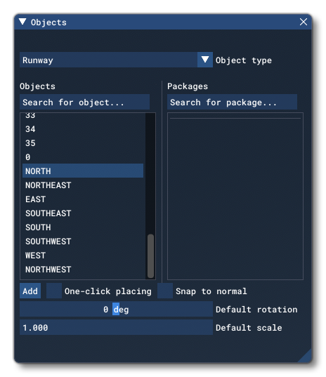
When you click the Add button, the Runway object will be added to the scene and can be positioned using the Gizmo. Once positioned, the runway can be edited.
IMPORTANT! Runway objects require one or more Airport Objects to be present in the scene, and must be added to an airport group in The Scenery Editor. If no airport is present then they cannot be used. Also note that if they are placed too far away (ie: outside the airport Object Test Radius) then they will not be rendered.
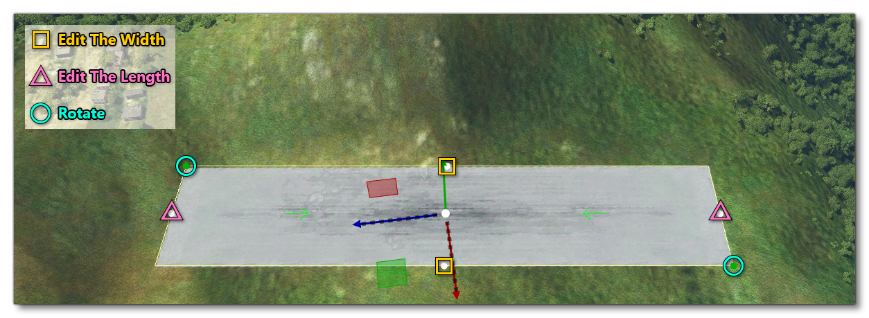
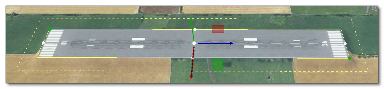
After adding the Runway object to the scene, its position, orientation and scale can be edited directly using the Gizmo in its center. You'll notice that there are various points shown on the runway area in the world view. Each of these points can also be clicked on, which will move the gizmo to that point and enable you to edit the following properties:
 Once you are happy with the placement of the runway, you can then go on to edit its Properties. Note that if you wish to remove the runway, you can select it and press
 Delete on the keyboard.
Note that runways will terraform the land that they are placed on so that they are on an even, flat surface. This behaviour can be edited using the Terraforming tools (as explained in the section below).
IMPORTANT! Certain objects have a Priority value (like polygons and aprons) which defines the order in which they are rendered. Lower priority objects will be rendered under higher priority objects. Runways do not have a Priority option but do have a priority value, which is 10 so they will generally render over everything else. Keep this in mind when setting priorities for other objects.
Properties
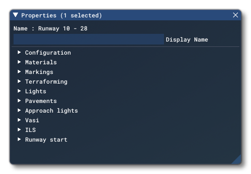
The Properties window for a Runway looks like this:
-
Name
This is the name of the element as defined from its type. The name will be appended with additional information depending on the rest of the options in the Properties window.
-
Display Name
This is the name of the element as it will be displayed in the The Scenery Contents List. This can be edited and is helpful for identifying elements when you have a lot of items in the content list.
The rest of the contents of the Properties window are explained in the sub-sections below.
Configuration
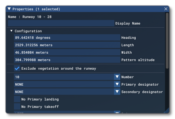
This section is related to the basic configuration of the runway. The available options are:
-
Heading
This value sets the direction (heading) of the runway, in degrees. It will be automatically updated if you edit the runway using the Gizmo directly in the scene.
-
Length
This value sets the length of the runway, in meters. It will be automatically updated if you edit the runway using the Gizmo directly in the scene.
-
Width
This value sets the width of the runway, in meters. It will be automatically updated if you edit the runway using the Gizmo directly in the scene.
-
Pattern Altitude
This value (also called the "circuit height") sets the altitude for aircraft to maintain a "holding pattern" for the runway, and is only relevant to AI air traffic. The value given is in meters and is offset from the actual runway altitude. For example, for a runway with an altitude of 2000m above sea level and a pattern altitude of 1500m, the aircraft would be flying at 3500m above sea level.
-
Exclude Vegetation Around The Runway
When checked, this will remove any vegetation from the scene in an extensive area around the entire runway area. When unchecked, vegetation can be right up to the edge of the runway (although not on the runway itself).
-
Number
This sets the runway number and can be a value from 1 to 36, or the words EAST, NORTH, NORTHEAST, NORTHWEST, SOUTH, SOUTHEAST, SOUTHWEST, or WEST.
-
Primary Designator
This is the primary designator of the runway being added. Can be any of the following values: L, R, C, A, B or Water.
-
Secondary Designator
This is the secondary designator of the runway being added. Can be any of the following values: L, R, C, A, B or Water.
-
No Primary Landing
When checked, the primary landing area of the runway will be disabled, meaning aircraft cannot land on that end. When enabled, aircraft can land on the primary end.
-
No Primary Takeoff
When checked, aircraft will not be permitted to take off from the primary end of the runway. Unchecking this will permit takeoffs.
-
Primary Pattern
The side for traffic patterns taking off from the primary end of the runway. Can be either LEFT or RIGHT.
-
No Secondary Landing
When checked, the secondary landing area of the runway will be disabled, meaning aircraft cannot land on that end. When enabled, aircraft can land on the secondary end.
-
No Secondary Takeoff
When checked, aircraft will not be permitted to take off from the secondary end of the runway. Unchecking this will permit takeoffs.
-
Secondary Pattern
The side for traffic patterns taking off from the secondary end of the runway. Can be either LEFT or RIGHT.
Materials
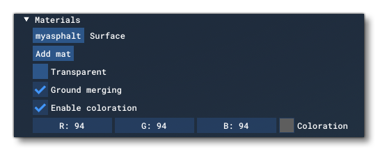
This section permits you to change the way a runway object will be rendered by applying one or more materials to it. You can select the Surface material to use by clicking the <MATERIAL> button to open The Material Editor, and then from there you can drag a material onto the button to apply it to the runway. Once applied, the button will change and show the name of the applied material.
IMPORTANT! When being rendered, runway elements are baked into the terrain textures. This helps reduce the polycount and permits the element to be terraformed. However, it also means that the texture quality won't be any greater than the resolution of the terrain textures themselves. In general, this resolution is around 4cm/pixel at the equator, with the best/highest resolution terrain textures reserved for higher LODs so we have a better quality for airports. For users, they will experience the best resolution possible setting the "Terrain level of detail" option to its maximum value.
The following options will be applied to the surface material, as well as any further materials you use (as explained below):
-
Transparent
Checking this will make the runway materials transparent so they won't be rendered in the scene, although the runway will still be valid and usable. Also note that even when a runway is flagged as transparent, its Markings will still be rendered.
-
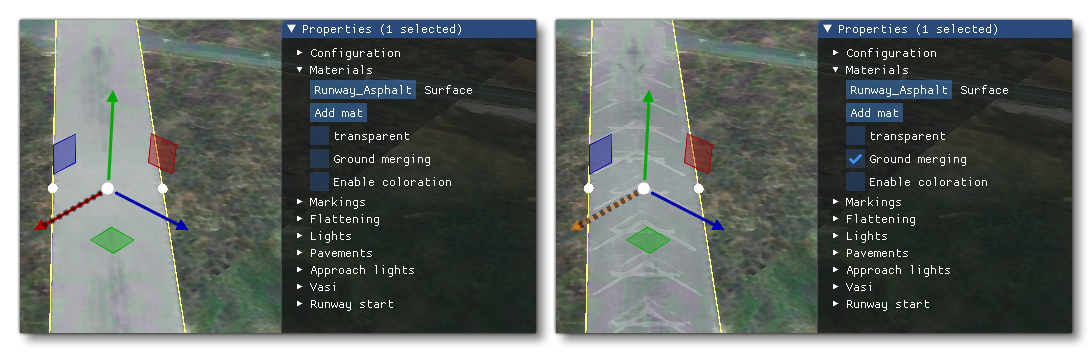
Ground Merging
When checked, this option will merge the terrain textures with the materials that are used for the runway.
-
Enable Colouration
Checking this will open a further set of options that permit you to edit the RGB values for the materials being used to texture the runway, using the color picker or by editing the value fields directly.
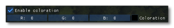 In this way you can change the color of the materials to better suit the environment and area that the runway has been placed in. Setting all the values to 0 will disable the colouration.
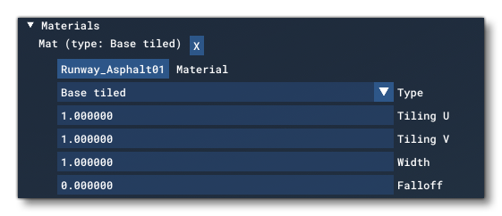
If you require more control over the visuals of the runway, you can click the Add Mat button instead of setting the Surface material. This button permits you to add multiple materials to the runway, and have each one behave in a different way, and it also gives you more control over how the material will be applied and rendered. Clicking this will present you with the following options:
 As before you have the
 <MATERIAL> button which can be used to open The Material Editor, and you can drag materials onto the button to apply them to the runway object. However, now you are not limited to a single material and add multiple materials as different types using the Add Mat button multiple times. Each material you add will have the following options:
-
Type
To help create unique, detailed and realistic runways you can add up to 7 different material types, each one adding a different visual "layer" to the final rendered runway. The table below explains each of these types and uses a special test texture to better illustrate how they work.
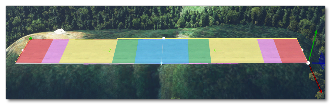
Test Texture Type Description Illustration Base Tiled This is the base surface material tiled along the length and width of the runway. Tiling will be based on the Tiling U/V values set. 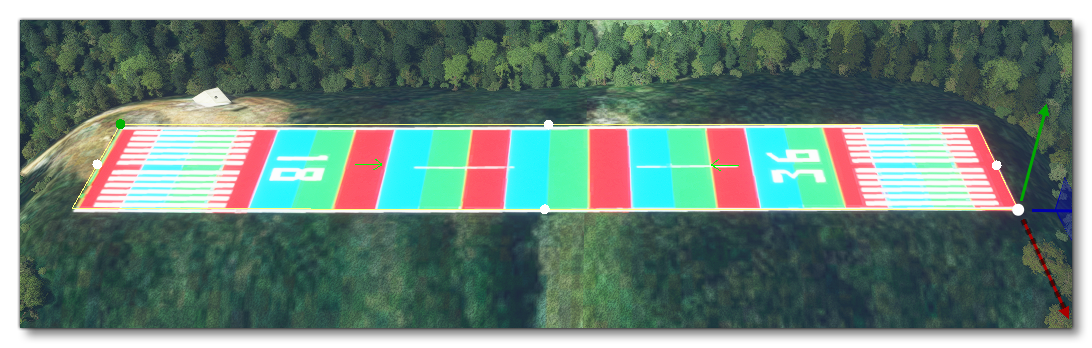
Base And Tire Marks This creates a base surface material stretched from both ends of the runway towards the middle. It is expected that the texture used for the material has tire marks included on it. 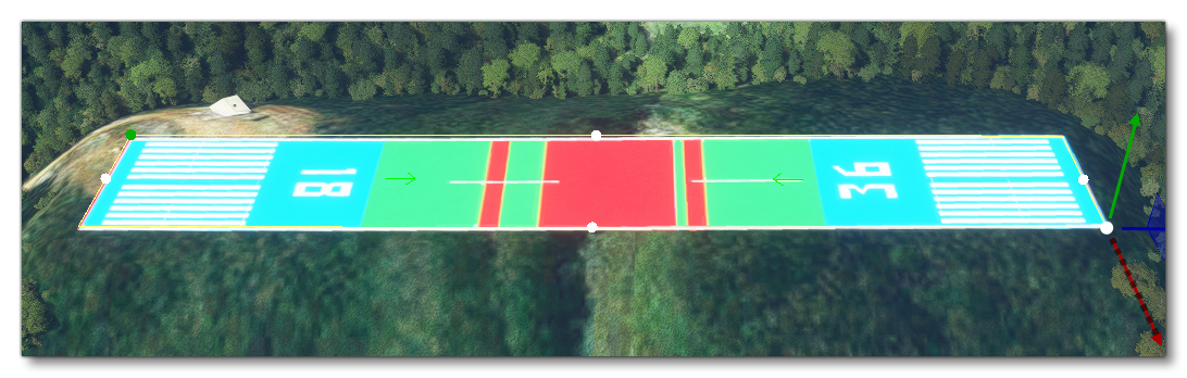
Base And End Cap This is a legacy format and requires the material texture to be laid out in a particular way (as shown in the image below). The texture will then be used in the way shown on the image to the right.
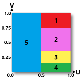 The sections of the texture are as follows:
- 1) Blast Pad - This section is tiled with v0.75 to v1.0 in the texture and will flip the texture back and forth in 150ft sections. This area is clear of any tire marks
- 2) Clear To Tires - This section goes from v0.75 to v0.35 in the texture. Goes from clear at the end to the middle of the black tire marks. There is no tiling here.
- 3) Black Tires - This section goes from v0.35 to v0.15 in the texture. The texture should have black tire touch down marks, and it will be repeated 8 times.
- 4) Black Tires To Center - This section goes from v0.15 to v0.0 in the texture. And is meant for adding black tire touch down marks to the center of runway. There will be no tiling performed using this part of the texture.
- 5) Center - This section takes half the texture width (u0.0 to u0.5), and when applied to the runway it will repeat an even number of times. When it repeats the texture will be "flipped" so that this section start and ends with
V==1.0.
Border This type is for adding a specific border texture to the runway and behaves essentially the same as the Based Tiled type, only it expects a texture that is transparent in the middle so it can be overlaid on the base surface. 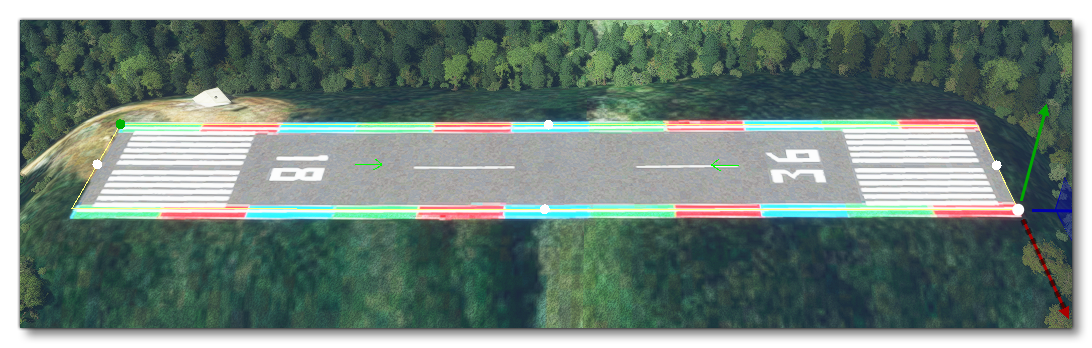
Center This type is for adding a specific center texture to the runway and behaves essentially the same as the Based Tiled type, only it expects a texture that is transparent along the edges so it can be overlaid on the base surface. 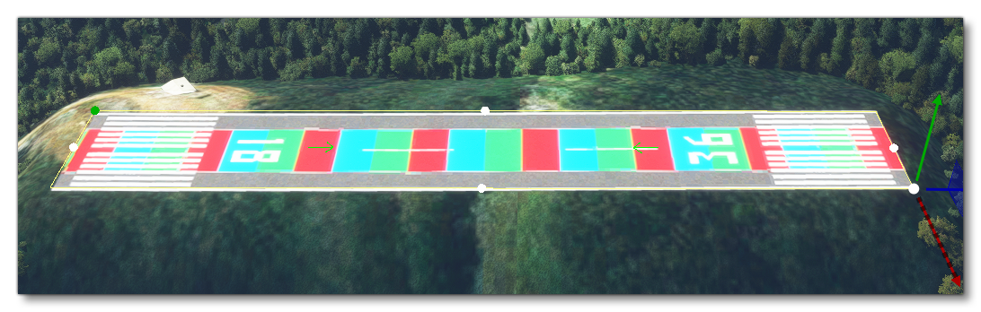
Patch This type is used to add imperfections to the runway like patches or damaged sections.
IMPORTANT! This type is currently not available and will be added in a future update.
Tire Gum This mode splits the texture in 3 parts and applies them in different proportions to the start and end of the runway to simulate tire marks on the ground. 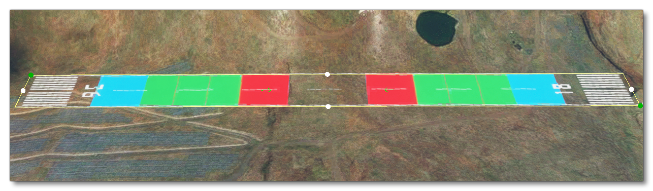
-
Tiling U
This sets the the texture to tile across the U axis (the runway width). By default this is set to 1.0 but you can change the value to alter the number of times the texture will be tiled.
-
Tiling V
This sets the the texture to tile across the V axis (the runway length). By default this is set to 1.0 but you can change the value to alter the number of times the texture will be tiled. Note that this may behave differently depending on the Type of surface material being added.
-
Width
Sets the width of the material texture in relation to the width of the runway. A value of 1.0 means the texture will be applied to fit the width of the runway, while a value larger than 1 will mean the texture will be stretched outside the bounds of the runway width. A value less than 1 will have the texture applied to a space smaller than the width of the runway.
-
Falloff
The falloff value is used to add "feathering" to the outer edges of the material after it is applied to the runway, creating a smoother transition between the runway material and the surrounding terrain or other objects.
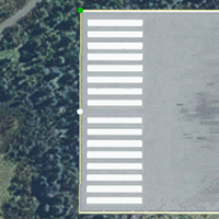
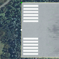
Markings
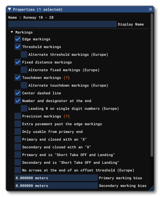
The next section in the Runway properties is for the runway markings. The table below shows each of the options:
| Markings / Alternate Markings | Illustration |
|---|---|
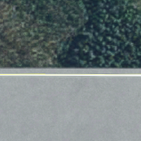
Edge Markings |
 |
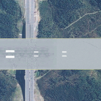
Threshold Markings / Alternate Threshold Markings(Mouse over the image to see the alternate version) |
  |
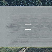
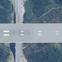
Fixed Distance Markings / Alternate Fixed Markings(Mouse over the image to see the alternate version) |
 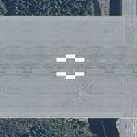 |
Touchdown Markings /Alternate Touchdown Markings(Mouse over the image to see the alternate version) |
  |
Center Dashed Line |
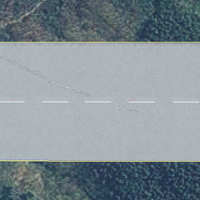 |
Number and Designator At End /Leading 0 On Single Digit Numbers(Mouse over the image to see the version with the leading 0) |
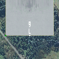 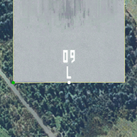 |
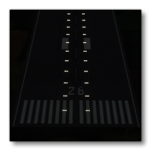
Precision Markings / Alternate Precision Markings(Mouse over the image to see the alternate version)
When this is selected, it will also activate the yellow light at the end of the runway. These lights will follow the FAA reglementation for their length. |
  |
Extra Pavement Past The Edge Markings |
 |
Only Usable From Primary End |
No Image Required. This simply removes any markings (number, designator, etc...) from the secondary end. |
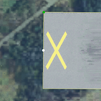
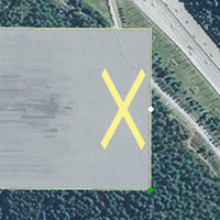
Primary End Closed With An "X" / Secondary End Closed With An "X" |
  |
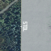
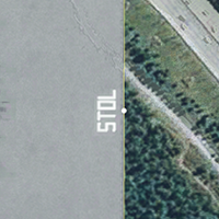
Primary End Is "Short Takeoff and Landing" / Secondary End Is "Short Takeoff and Landing" |
  |
No Arrows At The End Of The Offset Threshold(When checked, removes the arrows from the threshold pavement. Mouse over the image to see the difference) NOTE: This option requires a pavement threshold to have been set in the Pavement options (explained below). |
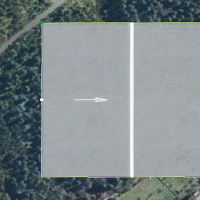 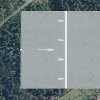 |
Underneath the different markings, you also have two values to set the Primary Marking Bias and Secondary Marking Bias. These values are in meters and are used to offset the primary or the secondary markings from their end of the runway.
Terraforming (Not available for World Hub Airports)
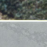
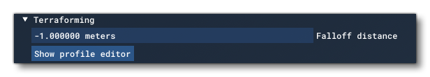 Initially, when you place a runway, the land that it is placed on will be automatically terraformed to flatten it and keep the runway on an even plane. However this can then be edited from this section. The most basic option available is the Falloff Distance (in meters) which is used to "feather" the edges of the terraforming to make the transition between the flattened runway and surrounding terrain less (or more) extreme. When setting this value, an extra set of lines will be rendered to show the area of the falloff, as illustrated in the image below:
To get more control over the slope of the runway you can also add a terraforming profile to it using the Add Profile button, which will then open the Profile Editor:
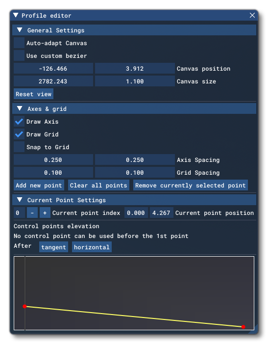
This editor is explained in full in the section on the page for Rectangle Objects. Any profile you create here will be applied to the runway object in the following way:
 When a runway object has a profile, the button will become
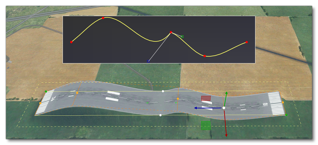
 Show Profile Editor, and clicking it will open the editor again so you may make any changes. To remove a profile, simply click the Clear All Points button in the Profile Editor. Once a profile has been created it will be applied to the runway, and you can see the different points in the simulation, as well as edit them in the world using the Gizmo instead of the Profile Editor:
Lights
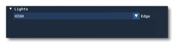 This section permits you to add basic runway lights to the object. Here you can set the Edge lights, choosing between the following three brightness levels (or NONE for no lights):
- LOW
- MEDIUM
- HIGH
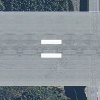
Pavements
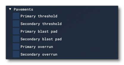
This set of options permits you to add additional pavement elements to the ends of the runway object. The available options are:
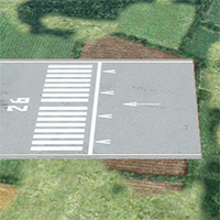
| Pavements | Illustration |
|---|---|
Primary Threshold / Secondary ThresholdNote that this will be added as part of the established runway length, and will not extend the runway. |
 |
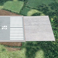
Primary Blast Pad / Secondary Blast PadThis will be added as an extension to the runway. |
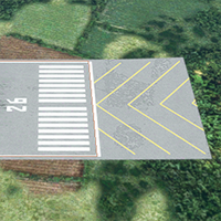 |
Primary Overrun / Secondary OverrunThis will be added as an extension to the runway. |
 |
Each one of these options has the following settings:
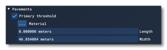
- Material: Clicking the
...button will open The Material Editor where you can choose an appropriate material to use for the selected option. You apply the material by dragging it from the editor and dropping it onto the button. This will then change to show the name of the chosen material and the runway visuals will update to apply it in the world. - Length: This sets the length (in meters) of the selected option.
- Width: This sets the width (in meters) of the selected option.
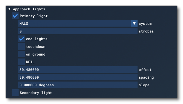
Approach Lights
Approach lights can be added to a runway using the Primary Lights Or Secondary Lights options for the primary and secondary end of the runway object. Enabling either of these will show you the following options:
-
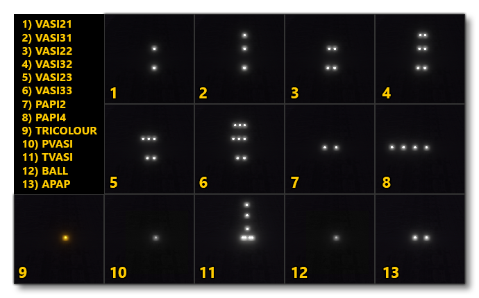
System
The lighting systems available are shown in the following image:
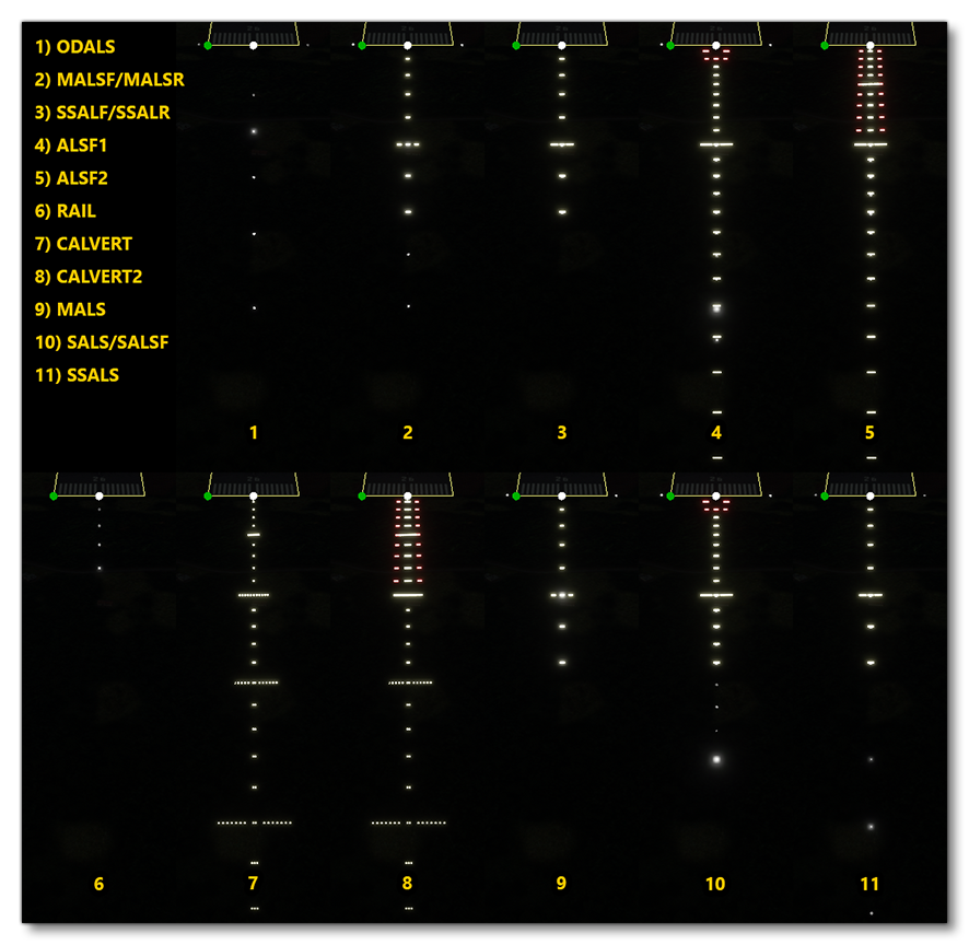
Note that the differences between the two system shown for each of the images 2, 3 and 10 is that the "F" version has strobes, while the other does not, but they are otherwise visually identical.
-
Strobes
This option sets the number of lead-in strobes for the runway approach lights. This value can be between 0 and 20 and would normally be set to 5 or more.
-
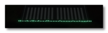
End Lights
Enabling this option will add a row of bright green lights to the end of the runway, marking the runway threshold.
-
Touchdown
Enabling this option will add a double row of lights to the runway itself.
-
On Ground
Enabling this option will place all the lights on the ground so that they follow the terrain. In general this is not ideal as it may mean that features on the terrain will block the lights.
-
REIL
Enabling this will add two blinking lights to the corners of the runway threshold. These lights are very high intensity and visible from far away, useful to see where the runway is from a distance.
-
Offset
This is the offset from the threshold of the runway, in meters. Changing this value will move the lights closer or farther away from the threshold edge.
-
Spacing
This is the spacing, in meters, between the approach lights. Changing this will change how far apart one light is from the other along the length of the light row(s).
-
Slope
This value is the slope angle, in degrees. Changing this will change the orientation of the entire row of lights, permitting them to be made more visible when the terrain is irregular around the threshold area.
VASI
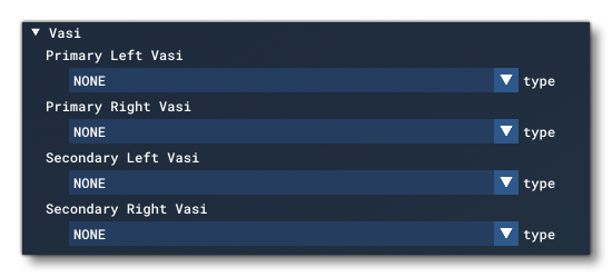 These options are for setting up different VASI systems for the Primary and Secondary ends of the runway, and can be configured for the Right or Left sides. Changing the type of any of the options will expand view to show further settings:
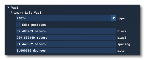
-
Type
The type of VASI lighting that should be used. One of the following:
-
Edit Position
When this option is enabled, the Gizmo moves to the VASI lights themselves and you can manually position them (only the translate gizmo can be used). Note that the position of the lights will be clamped to within certain bounds depending on the side and whether it is the primary or secondary runway being edited.
-
BiasX
This can be used to set the X-axis bias, in meters. Essentially this is the distance from the runway threshold, where 0 is on the threshold. Which threshold is used will depend on whether you are setting the value for the Primary or Secondary runway.
-
BiasZ
This can be used to set the Z-axis bias, in meters. Essentially this is the distance from the runway center, where 0 is on the center and greater values will move it towards the edge (which edge will depend on the side of the runway you are setting the value for).
-
Spacing
The value used here will set the spacing between the lights when there are multiple rows of VASI lights in the chosen type. Distance is in meters. Note that this is only applicable to the following systems: VASI21, VASI31, VASI22, VASI32, VASI23, VASI33, and TVASI.
-
Pitch
This value sets the VASI pitch, in degrees. The default value should be 3° but it can be changed to other values depending on the requirements of the airport/runway. Changes in this value will cause the VASI lighting to change color/pattern based on the approach slope of the aircraft.
ILS (Not available for World Hub Airports)
NOTE: Editing ILS data may invalidate all simulation NavData for the airport. Please see the following section for more information: Note On Navigation DataThis section is for setting up the ILS system for the Primary and Secondary runways. If you have an ILS reference then you can input that here:
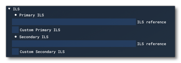
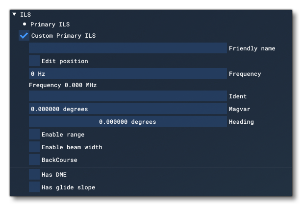
However if you wish create a custom ILS beacon then you can click on the Custom Primary / Secondary ILS checkbox which will first render a red in the world to represent the beacon you've enabled, and also present you with the following settings:
-
Friendly Name
Here you can give the beacon a name to make it easier to identify.
-
Edit Position
When this option is enabled, the Gizmo will move to the ILS beacon and you can manually position it in the world (only the translate gizmo can be used).
-
Frequency
This is the frequency in Hz for the beacon, and should be between 108000000Hz and 136992000Hz (108MHz and 136.992MHz).
-
Ident
Here you need to input the ICAO code beacon identifier. This should be a maximum of 5 characters and all capitals.
-
Magvar
This is the magnetic variation at the ILS beacon to True North. Negative for values to the east and positive for values to the west, measured in degrees between -360.0° and 360.0°.
-
Heading
The heading (magnetic bearing) of the main ILS beam, from 0.0° to 360.0°.
-
Enable Range
Enabling this permits you to set the range of ILS in meters. If this option is not enabled, then the default range will be used which is 50004m (27nm).
-
Enable Beam Width
Enabling this permits you to set the width of the ILS beam in degrees. If this option is not enabled, then the default value of 5.0° will be used.
-
Back Course
Enabling this indicates that the ILS beacon has a back course.
-
Has DME
When enabled, the ILS beacon will also have DME enabled and further options will be visible to permit you to Edit Position of the DME beacon - using the translate Gizmo in the world - and also set the Range.
-
Has Glide Slope
When enabled the ILS beacon will also provide glide slope guidance and further options will be enabled to permit you edit the Range and Pitch of the glide slope as well as enable the Edit Position option to use the translate Gizmo in the world to position the beacon.
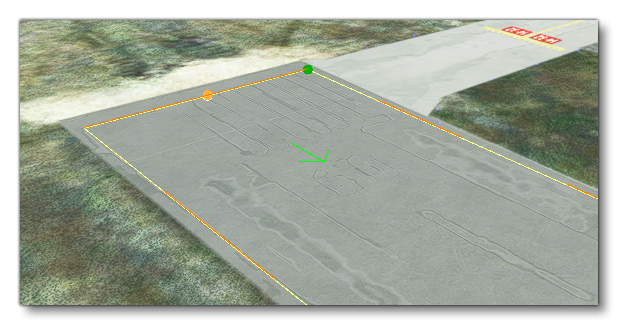
Runway Start
The start position for an aircraft on the runway will be shown as a green arrow pointing in the direction that the any aircraft starting there will face:
The actual position and heading for this start position can be set from the Runway Start options:
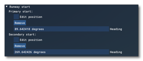
Here you can set the heading for the start position (relative to true North), or you can remove it using the Remove button, so that it will not be available as a start position for flights from the airport that has the runway. You can also edit the actual position by checking the Edit Position checkbox. This will set the Scenery Editor gizmo into "translate" mode and link it with the start position arrow in the editor. You can then use the gizmo controls to edit the position.