EXTERIOR LIGHTS
When adding lights to the aircraft model we use emissive meshes. as the basis for the light output and for Microsoft Flight Simulator 2024 the recommendation is to model lights with a high degree of fidelity, so the model should include not only the covering glass, but the LED's or filament that is underneath. In the following example you can see the navigation and strobe lights as modeled on the DA62:
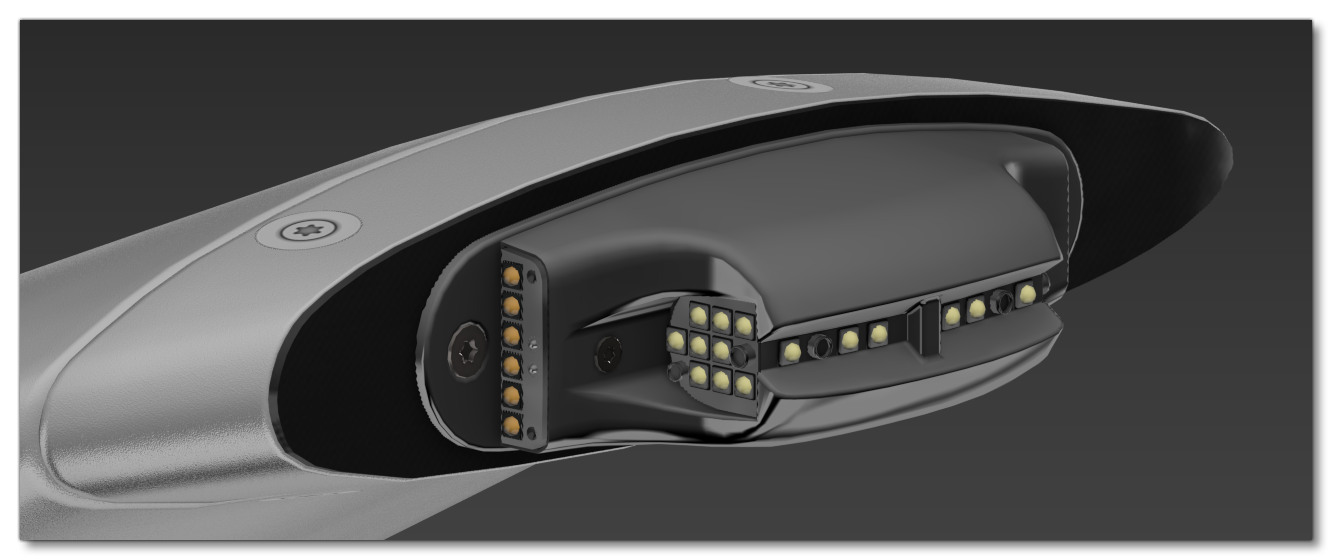
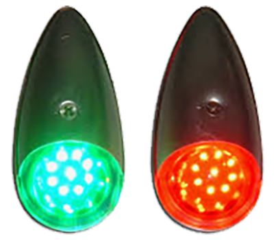
Note that many real aircraft lights are actually white and the colour they emit is created by the glass they are covered with. This is also a perfectly valid way to set up lights in your own models, as illustrated in the image below. Here the the emissive mesh for each LED is white, but the glass covering the LED's has been tinted red and green:
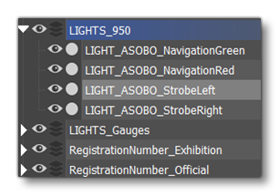
When it comes to the exporting of the model, the emissive meshes should be distinctly named and on a separate layer so that they can be exported correctly then used in the simulation. For example, if you have a wing light with two emissive meshes they would be called LIGHT_NavigationRed and LIGHT_StrobeLeft. They would be separated with a centered pivot and then have a Reset Xform applied to them. Once that has been done, they would then be placed onto a separated layer which would then be ticked in the multi exporter (and then they would be accessed in the CFG files for the aircraft).
It should be noted that in previous version of the simulation you would have needed to place helpers to ensure the light emitters were correctly placed when the aircraft was in the simulation, as these helpers would be referenced in the light definition. However, in Microsoft Flight Simulator 2024 this is no longer a requirement, and light emitters are actually placed in the simulation using The Edition Gizmo in The SimObject Editor. The exception to this is when the light is on a part of the plane that is animated. For example, if the light is on the rudder of the aircraft then you would need to set a dummy to be attached to the animated part (by making it child of it in the hierarchy), then name it appropriately, and then ensure that it is on the "Lights" layer for export. Finally you would need to mention the name of your helper in the Node section for the lightdef.N definition.
For information related to the setup of lights within the simulation, please see here:
Light Materials And Textures
Aircraft lights should be created as part of the airframe mesh and require the use a specific material to make them light up in the simulation following the guidelines given below.
Basic Setup
For the lights on your aircraft you will need to create a new material and call it "LIGHTS".
IMPORTANT! If you do not use "Lights" as the material name, then your lights won't work correctly when the aircraft is imported into the simulation.
This material is a Standard material, and uses the albedo (Base Color), Occlusion(R) Roughness(G) Metallic(B), and Normal textures. You can also supply an Emissive texture, which we'll discuss further down this page. The material itself should be set up as follows:
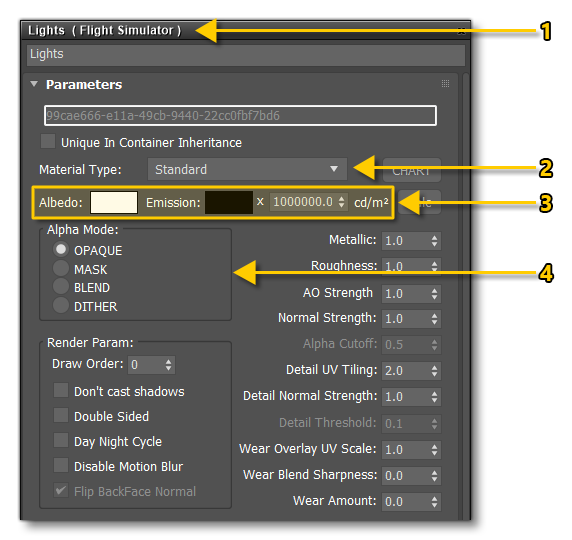
- Create a new FlightSim material and call it "Lights"
- Set the Material Type to Standard.
- Set the Albedo Colour, the Emissive Colour and the Emissive Multiplier.
- Set the Alpha Mode to Opaque.
This is the most basic setup that you can have for the light material, with the most important part to pay attention to being the Emissive value. When no emissive texture is supplied, this defines the RGB of the emissive colour, and you can use the value parameter (of the HSV section) to define the strength of the emissive:
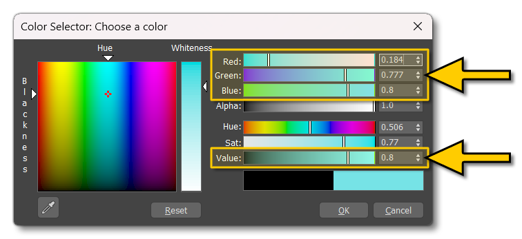
In this way you can pick the colour that you want for the light using the RGB values, and then adjust its brightness using theValue parameter. The approximate brightness for the value is shown in the image below:
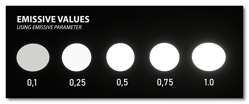
This is obviously not very bright for an emissive material and so you can augment this value using the Emissive Multiplier, which will increase the brightness and also the bloom from the emissive mesh (for more information on bloom see the Notes On Bloom section). In previous versions of the SDK this value was a simple multiplier from 0 to 100, however for Microsoft Flight Simulator 2024 this has now become an actual emission value in candela per meter², based on the correct mathematical principles that underly luminosity.
To better help you get the correct values for your lights, here are some real world examples of values that can be used for the emissive multiplier:
- Strobe Lights: The red/white anti-collision strobe lights on the aircraft should be a minimum of 400 candela.
- Landing Lights: These are usually exceptionally bright and one of the most used bulbs in aviation for landing lights outputs around 765,000 candela
- Taxi Lights: A common bulb used for taxi lights will have an output of about 90,000 candela.
As a final note, when setting up your materials you should only have one material per light type (emission value), and the different materials can all be part of a multi-material.
Using An Emissive Map
Instead of using the emissive Value and Multiplier values to generate the emissive, you can supply an Emissive Map as the Emissive texture of the material. It's important to note that the emissive value will have no effect when you supply an emissive texture, but the emissive multiplier will. This leads to the following situation:
- The light colour when the light is off will be defined by the albedo (Base Color) texture. Note that the UV mapping should not overlap for the lights which have different colors.
- The emissive colour when the light is on is defined by the Base Colour setting.
- The emissive value setting will not be used to set the emissive brightness, instead that will be set by the Emissive Map. When creating the emissive map, all the emissive elements should be 100% white on the texture, and the elements that aren't emissive should be black.
- The Emissive Multiplier value will modify the brightness.
Notes On Bloom
The bloom effect appears in-game when there is an emissive value strong enough to generate it. This effect is not directly controllable but can be modified by changing the emissive value or the emissive multiplier value. The following things are worth noting about this effect:
- Bloom appears only when a pixel of an emissive zone is visible by the player. However, as there are no real photons being emitted, it is possible that the bloom effect will disappear when viewed by the user at a tight angle, even though the emissive emissive zone (like a bulb) can be seen.
- Bloom is linked to the emissive value intensity and the size of the emissive zone, such that:
- a stronger value - especially in the Emissive Multiplier - will generate more bloom.
- a larger emissive zone will generate more bloom.
- Bloom can also be reduced and affected by some external parameters:
- a glass material with an albedo map will reduce the bloom effect, and more dark colours in the albedo map means more reduction in bloom.
- the windshield material will also reduce the visible bloom effect from lights by a small amount.
- Bloom quality is affected when we look at it through a glass material (whatever its parameters), however this quality reduction is only really visible when the emissive source is viewed up close.
Sky Portals
Sky portals are a kind of light that is applied to the exterior of all windows that show any interior and that simulate additional sunlight in a way which gives improved visual fidelity to the characters within the aircraft. To add these kinds of light sources, you will first need to add a Sky Portal light in your modelling software (this will have been added to your tools when you installed the SDK Plugins).


When added to the scene the Sky Portal light will be shown with two concentric circles, and it's the inner circle that is the actual portal, and any windows the light is placed over should encompass this circle completely, and the "dome" (3DS Max) or "direction" (Blender) should be pointing inside the aircraft. The inner circle is defined using the inner angle parameter for the light in 3DS Max / Blender, and thew outer angle should always be set to 180.
The image below shows the right and wrong way to set this up in your modeling software:

You should ensure that each portal is included on a sub-layer of the element that will be getting exported, for example, if you are adding portals to the fuselage, then these would be on a sub-layer of the x0 LOD for the fuselage, so they are all exported along with that part of the aircraft. The image below shows the fuselage setup for an airliner where passengers will be added later, and so each window requires a Sky Portal:

Setting Ambient Occlusion Values
Adding the Sky Portals to the model is not enough to ensure that the lighting is correct on the interior character models, and once the model is finished and exported, you will also need to "tweak" the ambient occlusion settings for the nodes where the passengers, copilot and pilot will be seated. This is done using the node_occlusion_factor parameter from the navigation_graph.cfg:

Character AO should be similar, or even a little darker, to the interior scene. The image below shows the difference that the combination of a Sky Portal with good AO settings can make to a scene. It's subtle, but greatly improves the immersion of the visuals (mouse over the image to see the effect):


It should be noted that, as with any other type of light, Sky Portals can be debugged in the simulation using the Lights option in the SimObject Debug Menu.
Related Topics