IMPLEMENTING LIGHTS
The lights on a SimObject are created through a combination of modelling, texturing, and the use of an *.fx file in combination with other parameters and files within the SimObject package. On this page you can find information on how to setup the files that your lights will require, as well as how to setup the electrics system correctly.
For information on the correct modeling and texturing of lights please see the Exterior Lights and Cockpit And Cabin Lights sections.
File Setup
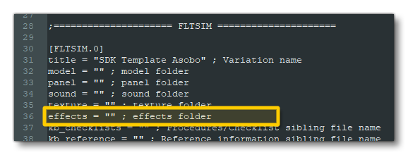
To start setting up the SimObject package for your lights you will first need to define the folder where the light effects files are going to be placed. For that you need to add the relative folder path for the *.fx files into the aircraft.cfg file. If this is the default "effects" folder, then you can leave it as an empty string (or omit it completely which has the same result), as shown in the following image:
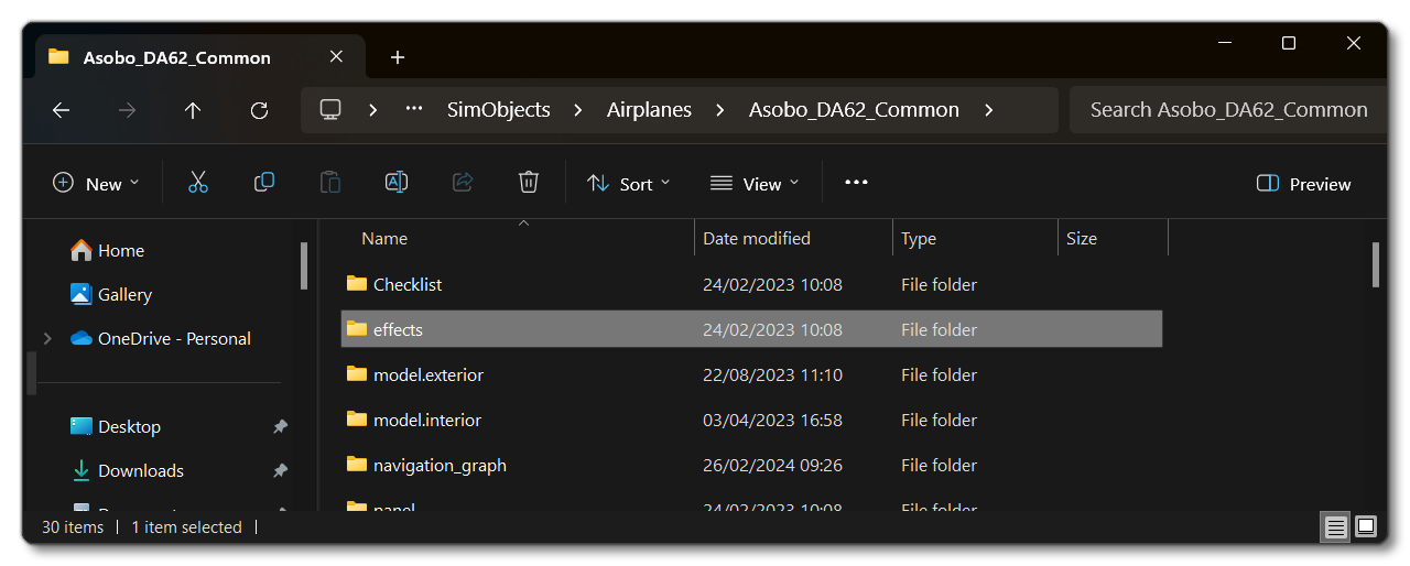
The image below shows a typical folder structure for an aircraft SimObject with this folder:
If you are not using the default folder, then the name you give in the aircraft.cfg file will need to be appended onto the "effects" folder name and that is the folder that will be checked. For example, if we had this in the configuration file:
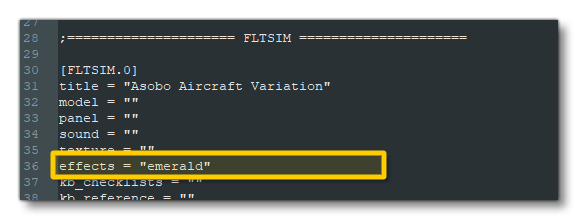
Then we would also have the following folder for the SimObject:

Once you have set up the effects folder, you can go ahead and place your light effects files in it (you can find information on the *.fx file format here). These effects can then be referenced in the lightdef.N parameter of the of the systems.cfg file. Note that you may also need to include an optional texture folder within the effects folder, depending on the requirements of the lights. This folder will hold any files that the lights use for sprites - *.png or *.bmp format, and each texture in the folder should have a <texture_name>.xml file associated with it.
The FX File
The full properties of the FX file are explained on the Light FX Properties page, but in general you will need to set up the following for each effect that you want to use in the aircraft:
-
[Particle.0]
This section is only used if you supply a texture for sprite billboarding.
-
[ParticleAttributes.0]
This section is used to define the colour and "look" of the light, and is also where you can supply the texture to use as a billboard sprite. Note that you do not need to supply a texture for the light to be visible, as this section is also used to define the light emission and colour, however, the light may not be visible enough at distance if a billboard sprite texture is not supplied (see the Note On Exterior Light Flares for more information).
-
[LightAttributes.0]
This section further defines how the light will shown in the simulation. All of the parameters here should be set for the light to work correctly.
It should be noted that you do not have to create your own FX files, and can use the built-in effects instead. You can find a list of those that can be used here:
Light Setup
Having set up the file and folder structure in the SimObject package, you will need to set up the light parameters to control them. The first thing to do would be to create circuits for each type of light in The SimObject Editor Systems tab, under the Electrical section:
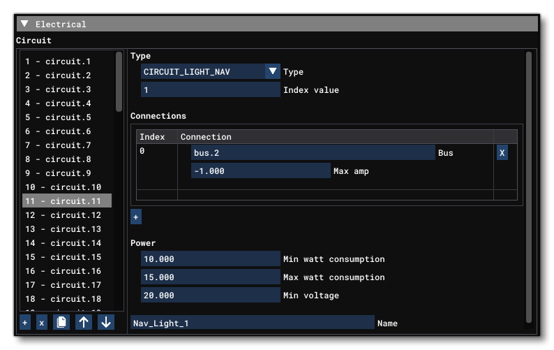
Usually you would name the circuits according to the lights they will be controlling, and you would also include - along with the name - an index that matches with the light index (if you need multiple lights of that type). This is written to the system.cfg (as outlined here: circuit.N):
[ELECTRICAL]
...
circuit.12 = Type:CIRCUIT_LIGHT_NAV # ConsumerCfg:ConsumerCircuitB # Name:LightNav
circuit.13 = Type:CIRCUIT_LIGHT_BEACON # Voltage:28 # Amperage:0.26 # Name:LightBeacon
circuit.14 = Type:CIRCUIT_LIGHT_LANDING # Voltage:12 # Wattage:30 # Name:LightLanding
circuit.15 = Type:CIRCUIT_LIGHT_TAXI # Voltage:12 # Wattage:35 # Name:LightTaxi
circuit.16 = Type:CIRCUIT_LIGHT_STROBE # Voltage:12 # Wattage:25 # Name:LightStrobe
circuit.17 = Type:CIRCUIT_LIGHT_GLARESHIELD # ConsumerCfg:ConsumerCircuitA # Name:LightGlareShieldA
circuit.18 = Type:CIRCUIT_LIGHT_GLARESHIELD # ConsumerCfg:ConsumerCircuitA # Name:LightGlareShieldB
circuit.19 = Type:CIRCUIT_LIGHT_WING # ConsumerCfg:ConsumerCircuitB # Name:LightWing
circuit.20 = Type:CIRCUIT_LIGHT_LOGO # ConsumerCfg:ConsumerCircuitB # Name:LightLogo
circuit.21 = Type:CIRCUIT_LIGHT_CABIN # ConsumerCfg:ConsumerCircuitC # Name:LightCabinA
circuit.22 = Type:CIRCUIT_LIGHT_CABIN # ConsumerCfg:ConsumerCircuitC # Name:LightCabinB
circuit.23 = Type:CIRCUIT_LIGHT_CABIN # ConsumerCfg:ConsumerCircuitC # Name:LightCabinC
circuit.24 = Type:CIRCUIT_LIGHT_PEDESTAL # ConsumerCfg:ConsumerCircuitA # Name:LightPedestal
...
Once you have set up the light circuits, you then need to add in the actual light definitions. This is also done through The SimObject Editor Systems tab, using the lightdef.N parameter, where each definition N is a single light: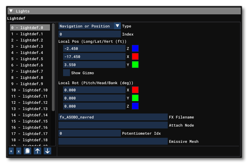
Generally the artists would set up the lights when implementing them art side - which may include creating a light *.fx file, along with sprite textures - but the parameters will need to be modified later such that the Index and the Potentiometer (and the light type, if incorrect) can be adjusted to behave properly. When saved from the aircraft editor, the system.cfg file will look something like this:
[LIGHTS]
lightdef.1 = Name:COCKPIT_Screen_Blue_Left #Type:13 #Index:0 #LocalPosition:-1.2,-0.8,1.8 #LocalRotation:0,0,180 #EffectFile:LIGHT_ASOBO_ScreenBlue #PotentiometerIndex:12
lightdef.2 = Name:COCKPIT_Screen_Blue_Right #Type:13 #Index:0 #LocalPosition:-1.2,0.6,1.8 #LocalRotation:0,0,180 #EffectFile:LIGHT_ASOBO_ScreenBlue #PotentiometerIndex:13
lightdef.3 = Name:COCKPIT_EFB #Type:13 #Index:0 #LocalPosition:-1.87,0.24,2.53 #LocalRotation:25,0,180 #EffectFile:LIGHT_ASOBO_ScreenBlue #Node:"" #PotentiometerIndex:13 #EmMesh:"" #EmMeshMaterialName:LIGHTS
lightdef.4 = Name:COCKPIT_Spot_Overhead_01 #Type:10 #Index:2 #LocalPosition:-3.89,0.21,3.125 #LocalRotation:50,0,-40 #EffectFile:LIGHT_ASOBO_Spot_Large #PotentiometerIndex:0 #EmMesh:LIGHTS_Asobo_Overhead_01 #EmMeshMaterialName:LIGHTS_02
lightdef.5 = Name:COCKPIT_Bounce_SpotOverhead01 #Type:13 #Index:0 #LocalPosition:-3,-0.7,2.2 #LocalRotation:0,0,0 #EffectFile:LIGHT_ASOBO_Bounce_Middle #Node:"" #PotentiometerIndex:11 #EmMesh:""
lightdef.6 = Name:COCKPIT_Spot_Overhead_02 #Type:10 #Index:1 #LocalPosition:-3.89 #LocalRotation:50 #EffectFile:LIGHT_ASOBO_Spot_Large #PotentiometerIndex:0 #EmMesh:LIGHTS_Asobo_Overhead_02 #EmMeshMaterialName:LIGHTS_02
lightdef.7 = Name:COCKPIT_Bounce_SpotOverhead02 #Type:13 #Index:0 #LocalPosition:-3,0.7,2.2 #LocalRotation:0,0,0 #EffectFile:LIGHT_ASOBO_Bounce_Middle #PotentiometerIndex:11
lightdef.8 = Name:COCKPIT_Spot_Overhead_03 #Type:10 #Index:3 #LocalPosition:-4.9,0.15,3 #LocalRotation:90,0,180 #EffectFile:LIGHT_ASOBO_Spot_Large #PotentiometerIndex:0 #EmMesh:LIGHTS_Asobo_Overhead_03 #EmMeshMaterialName:LIGHTS_02
Note that when you are using the SimObject editor, it's possible to place lights within the simulation itself using The Edition Gizmo. This is further simplified by enabling the lighting debug options, available from the Lights option in the SimObject Debug Menu, which will show the direction and cone of any lights that are being placed.
Finally, in the aircraft model.xml file you can use an existing model behaviour template (usually one with the format ASOBO_LIGHTING_<switch/push>_Light_<light type>_Template, which you can find here: Lighting.xml), or you can make your own template for the interaction.
Once you have your model behaviors set up, check you are correctly triggering the electrical system and that the indexed SimVar takes the correct value, or that you are using the right potentiometer index. If the light still does not work - ie: nothing is showing - then this is probably a problem on the art side of things. However, you can check by using the User Lights debug window and toggling the effect manually from there:
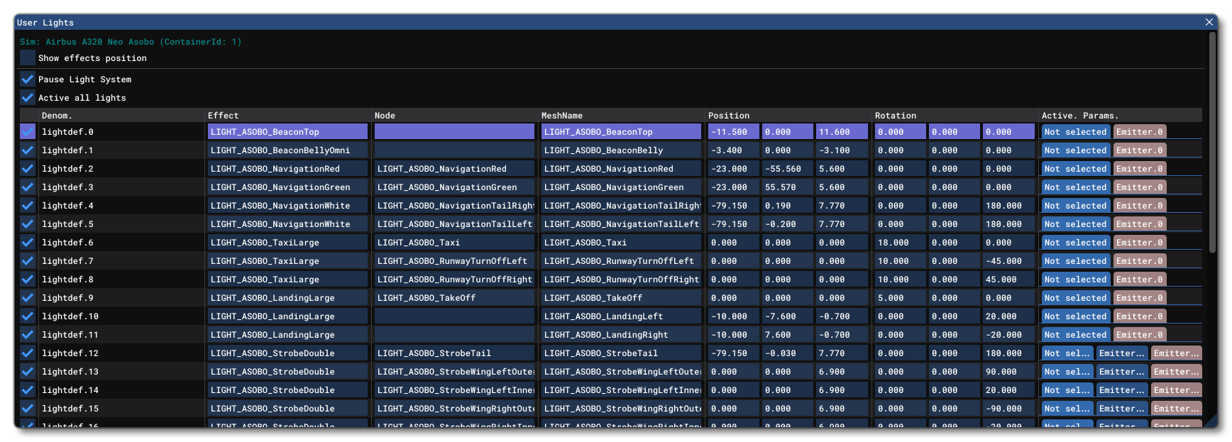
If the light still doesn't work when using this debug window, there is a high chance something is wrong with the light itself (effect mesh, orientation, node attached, FX file, etc...).
Note For Glass-Cockpit Emissive Elements
Implementing Glass-Cockpits is a complex subject that has been separated into its own set of tutorials which you can find from the following links:
However, it's worth taking a moment to note how you use emissive textures within the glass-cockpit display. This is done through the model behavior XML, using a template that can affect a material's emissive, such as ASOBO_GT_Component_Emissive_Gauge.
IMPORTANT! Make sure the #EmMesh setting in the lightdef.N parameter is an empty string "" when working with panel and interior lights. Interior controlled lights using the Model Behavior system conflict with the #EmMesh setting and the emissive simply will not work if an emissive mesh is referenced.
The easiest way to handle a screens emissive elements is to create [LocalVars] that contains a percentage of brightness between 0 and 1. That percentage can then be connected to a knob which will be used to control it. The value can also be multiplied using the SimVar GLASSCOCKPIT AUTOMATIC BRIGHTNESS, which has a factor value that changes depending on the time of day, for example:
<Template Name="MyScreenTemplate">
    <DefaultTemplateParameters>
        <BRIGHTNESS_VARIABLE_TYPE>L</BRIGHTNESS_VARIABLE_TYPE>
        <BRIGHTNESS_VARIABLE_NAME>XMLVAR_#PREFIX#_#ID#_Brightness</BRIGHTNESS_VARIABLE_NAME>
    </DefaultTemplateParameters>
    <UseTemplate Name="ASOBO_GT_Component_Emissive_Gauge">
        <NODE_ID>#NODE_ID_SCREEN#</NODE_ID>
        <EMISSIVE_CODE>(#BRIGHTNESS_VARIABLE_TYPE#:#BRIGHTNESS_VARIABLE_NAME#) (A:GLASSCOCKPIT AUTOMATIC BRIGHTNESS, Percent over 100) *</EMISSIVE_CODE>
    </UseTemplate>
</Template>
Note On Exterior Light Flares
In Microsoft Flight Simulator 2024, exterior lights have a post-processing effect added to generate a light flare, for example:
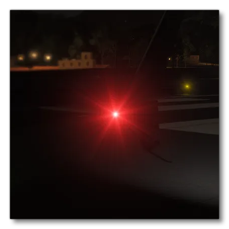
This effect will be active on all exterior lights and is affected by the following parameters:
- The
Sizeand theIntensityof the light, where the size corresponds to the size of the emissive zone of your light (in meters), and the intensity corresponds to the strength of the light (in candela). -
The
Color_StartandColor_Endof the light. Note that we recommend you avoid the use of pure colors in the RGB values, for example, when creating a green navigation light it is tempting to simply use (0, 255, 0), however you will get a much better effect when you set the values to (10, 255, 10). -
The Softness parameter should be less than 1. If set to 1 the flare will not be displayed nor will the light be reflected in specular of objects that are illuminated by it. The light will still work and be shown in the simulation when viewed directly.