AIRPORT XML PROPERTIES
This page lists most of the different elements and attributes required to generate properly formed XML for an airport. Most of the XML shown, is created for you when you use The Scenery Editor tool - included as part of the Developer Mode toolset within Microsoft Flight Simulator 2024. As such, we recommend that you use that tool instead of trying to create your own XML from scratch, and use this page as a reference if you need to edit the files the Scenery Editor creates.
IMPORTANT! When doing work on an already existing airport in the simulator, by default the behavior is to add the new set of data to the existing airport and not to replace the corresponding data. If the objective is to replace the previous set of data, then it is necessary to use a <DeleteAirport> element to describe what is to be replaced.
Note that this page covers the XML required for the airport and some of it's facilities, but other things like runways and approach routes are not included here to keep the information in more manageable blocks. The links below cover the things that are not included on this page, and all of them would be used within the <Airport> container element:
Finally, the XML document for an airport must have the following format:
<?xml version="1.0" encoding="utf-8"?>
    <FSData version="9.0">
        <Airport>
            <!-- Airport Data Elements Here -->
        </Airport>
    </FSData>
<FSData>
The <FSData> element is the top level container which contains the <Airport> sub-element (and can also contain various other Scenery Editor Object XML elements). It has the following possible attributes:
| Attribute | Description | Type | Required |
|---|---|---|---|
|
|
The current version of the XML file. IMPORTANT! The |
String | Yes |
|
|
The file timestamp. | String | No |
|
|
The patch number for the file. | String | No |
|
|
The original source of the file. | String | No |
<Airport>
The <Airport> element is used to indicate the placement of airport facility information. Airports are placed according to their airport reference point and may contain a large amount of data, with the element containing one or more of the following sub-elements:
<AirportArchetype>
<ApronControl>
<Tower>
<Services>
<Com />
<Runway>
<RunwayAlias>
<Ils>
<Aprons>
<PaintedElements>
<DetailPolys>
<ApronEdgeLights>
<LightPreset>
<LightSupport />
<AirportGroup />
<Group>
<TaxiwaySign />
<TextMarking>
<Waypoint>
<Departure>
<Arrival>
<Approach>
<Ndb>
<Helipad>
<Start />
<Jetway>
<VDGS>
<ProjectedMesh>
<VectorPlacement>
<BlastFence>
<BoundaryFence>
<DeleteAirport>
<HoldingPattern>
<WasmModule />
The following elements are also used in the creation of airports, and - if used - they must be defined in the given order:
<TaxiwayPoint /><TaxiwayParking /><TaxiwayParking /><TaxiwayServiceStand /><TaxiName /><TaxiwayPath>
The airport element has the following attributes:
| Attribute | Description | Type | Required |
|---|---|---|---|
|
|
The display name for the object in the Scenery Editor. NOTE: this is only used for ordering in the The Scenery Contents List |
String | No |
|
|
The ID of the parent group this object belongs to. NOTE: this is only used for ordering in the The Scenery Contents List |
Integer | No |
|
|
The group index of the object. NOTE: this is only used for ordering in the The Scenery Contents List |
Integer | No |
|
|
The group ID of the object. NOTE: this is only used for ordering in the The Scenery Contents List |
Integer | No |
|
|
Whether the group has been auto-generated or not. NOTE: this is only used for ordering in the The Scenery Contents List |
Boolean | No |
country |
This is the name of the country the airport is in. This string can be localised using the TT:<VARIABLE_NAME> format, as explained in the LOC Files (Localization) documentation. |
String | No |
state |
This is the name of the state the airport is in. This string can be localised using the TT:<VARIABLE_NAME> format, as explained in the LOC Files (Localization) documentation. |
String | No |
city |
This is the name of the city that the airport is either in or nearest to. This string can be localised using the TT:<VARIABLE_NAME> format, as explained in the LOC Files (Localization) documentation. |
String | No |
name |
This is the name of the airport itself and will be displayed to the user. This string can be localised using the TT:<VARIABLE_NAME> format, as explained in the LOC Files (Localization) documentation. |
String | No |
region |
The region the airport is in. Generally the region would be one of the following:
|
String | No |
regionCode |
This is the ICAO country code which must be a maximum of two characters. See here for more information. |
String | No |
lat |
Latitude of the airport reference point, in degrees between -90.0° and 90.0°. |
Float |
Yes |
lon |
Longitude of the airport reference point, in degrees between -180.0° and 180.0°. | Float | Yes |
alt |
Altitude of the airport reference point, in meters. You may add the "F" suffix to convert the value to feet, for example: "13.0F". |
Float |
Yes |
altType |
This is used to determine the referential for the alt field. |
Enum:
|
No |
magvar |
Magnetic variation, the angle difference between the magnetic north and true north. Negative for value to the east and positive for value to the west, measured in degrees between -360.0° and 360.0°. | Float | No |
ident |
This is the ICAO code for the Airport being defined, and is used to represent the airport in multiple places. Must be between 3 and 8 characters long, eg: "UUWW". |
String | Yes |
airportTestRadius |
Airport test radius in meters. You may add the "F" suffix to convert the value to feet, for example: "1300.0F". This is the distance around the airport reference point (location) that will be tested for airport object elements. Anything that is an airport element that is outside this area may cause build errors. | Float | No |
trafficScalar |
The volume of AI traffic that is appropriate for this airport. 1.0 would apply to major airports. NOTE: This is a deprecated feature and the value added for this attribute will have no effect in the simulation. |
Float | No |
isOnTIN |
Used to get a different ground materials behavior in certain area. | Boolean | No |
tinColorCorrection |
This option applies colour correction to certain airport features - mainly runways and aprons - to eliminate unnatural TIN colours bleeding into them. Mouse over the image below to see an example of the difference this option can make (note that the difference will depend on the location):   This is enabled by default. |
Boolean | No |
onlyAddIfReplace |
Only adds the airport if it was already present in another package. Relevant if the data contained within <Airport> is only complementary and not meant to be used on its own. |
Boolean | No |
applyFlatten |
Generate flattening rectangles on the airport based on runways altitude and inclination. | Boolean | No |
starAirport |
Puts the airport forward on the world map. | Boolean | No |
closed |
Stop the airport from being accessible or interactive in any interface such as the world map, the instruments or the ATC system. The airport is only going to be rendered in the simulator.. | Boolean | No |
groundMergingTransfertBright |
Ground merging bright setting. | Float | No |
groundMergingTransfertDark |
Ground merging dark setting. | Float | No |
uuid |
This is a unique identifier used by some mission parameters. | String | No |
transitionAltitude |
This defines the transition altitude - the altitude above sea level at which aircraft change from the use of local pressure to the use of standard pressure - for the airport, in ft. | Float | No |
transitionLevel |
Defines the transition level - the height above sea level that flight level is used instead of feet or meters - for the airport, in ft. | Float | No |
<AirportArchetype>
This a sub-element of the <Airport> element and is used to
This element has the following attribute:
| Attribute | Description | Type | Required |
|---|---|---|---|
|
|
The GUID for this archetype override. | String | No |
<ParamOverride />
This is a self-closing sub-element of <AirportArchetype> and is used to define a single parameter to override and the value to override it with. You may include multiple of these elements to override several of the available properties for any airport, for example:
<AirportArchetype>
    <ParamOverride name="RunwayTireGumOpacity" value="0.0"/>
    <ParamOverride name="RunwayCrackOpacity" value="0.0"/>
    <ParamOverride name="RunwayPatchOpacity" value="0.0"/>
    <ParamOverride name="RunwayGroovingOpacity" value="0.0"/>
    <ParamOverride name="AsphaltDirtOpacity" value="0.000"/>
    <ParamOverride name="TaxiwayTireStainOpacity" value="0.0"/>
</AirportArchetype>
This element has the following attributes:
| Attribute | Description | Type | Required |
|---|---|---|---|
|
|
The name of the parameter (as a string) to override the value of. See the Override Parameters List for all the available override parameters. For a visual representation of the changes these parameters will make to the airport see here: Airport Archetype Overrides | String | Yes |
value |
The value/string to override the base parameter with. | Mixed | Yes |
Override Parameters ListOverride Parameters List
The table below lists all the parameters that can be used as override parameters in the <ParamOverride /> element:
| Parameter String | Description | Type | Unit |
|---|---|---|---|
TrafficDensity |
This will change the density of airport traffic (ambient vehicles) around, where 0 is no traffic and 1 is the maximum amount permitted for the airport category. | Float | N/A |
TrafficVarietyAirportCategory |
This sets the category of traffic (ambient vehicles) to override, where each value corresponds to an existing airport archetype. | Integer Constant |
0: Extra Small Airport 1: Small Airport 2: Medium Airport 3: Large Airport 4: Extra Large Airport 5: Extra Extra Large Airport |
TaxiwayTireGumOpacity |
This will change the opacity (alpha) of the tire gum decal, and should be between 0 (invisible) and 1 (fully opaque). Default value is 0. |
Float | Percent Over 100 |
TaxiwayTireGumMaterial |
This parameter lets you override the default tire gum material with another one from The Material Editor. You supply the GUID of the material to apply, as a string. | String | GUID |
TaxiwayTireGumTiling |
This parameter lets you change the amount that the tire gum decal material is tiled. Default value is 1. | Float | N/A |
TaxiwayTireGumMinCount |
This value sets the minimum number of tire gum decals that can be overlaid (the actual amount will be a random number between the min and max count values). Default value is 1. |
S32 Integer | N/A |
TaxiwayTireGumMaxCount |
This value sets the maximum number of tire gum decals that can be overlaid (the actual amount will be a random number between the min and max count values). Default value is 1. |
S32 Integer | N/A |
TaxiwayTireGumRandomRotation |
This value sets the variation in angle for each of the overlaid tire gum decals. Default value is 0. |
Float | Degrees |
TaxiwayTireGumRandomTranslate |
This value sets the variation in the translation offset for each of the overlaid tire gum decals. Default value is 0. |
Float | Meters |
TaxiwayTireGumMeanWidth |
This value can be used to control the mean/average width over which the tire gum decals will be applied. Default is 20. |
Float | Meters |
TaxiwayTireGumMinDensity |
This value sits the minimum density for the tire gum decals. Default value is 1. |
Float | N/A |
TaxiwayTireGumMaxDensity |
This value sits the maximum density for the tire gum decals. Default value is 1. |
Float | N/A |
RunwayTireGumOpacity |
This will change the opacity (alpha) of the decal, and should be between 0 (invisible) and 1 (fully opaque). | Float | Percent Over 100 |
RunwayTireGumOpacityVariance |
This will change the amount of random variance in the decal opacity (alpha) that is applied, from 0 (no variance) to 1 (full variance). | Float | Percent Over 100 |
RunwayTireGumMaterial |
This parameter lets you override the default material with another one from The Material Editor. You supply the GUID of the material to apply, as a string. | String | GUID |
RunwayTireGumWidth |
This parameter controls the relative width of the tire gum decal on the runway, where 1 is the un-scaled base decal width, 0.5 would be half the decal width, and 2 would double the decal width. Default value is 1. |
Float | Scalar |
RunwayTireGumTilingV |
This parameter sets the horizontal tiling amount for the tire gum decal material. Default value is 1. |
Float | N/A |
RunwayTireGumAimingPointRatio |
This parameter sets the distance ratio from the runway aiming point after which the tire gum decal should be stretched. A ratio of 1 will have the decal stretched after the aiming point the same amount as before, 0.5 will be half that distance, 2 will be double that distance. Default value is 1. |
Float | Scalar |
RunwayCrackOpacity |
This will change the opacity (alpha) of the decal, and should be between 0 (invisible) and 1 (fully opaque). Default value is 0. |
Float | Percent Over 100 |
RunwayCrackMaterial |
This parameter lets you override the default material with another one from The Material Editor. You supply the GUID of the material to apply, as a string. | String | GUID |
RunwayCrackMaterialTiling |
This parameter lets you change the amount that the decal material is tiled. Default value is 1. |
Float | N/A |
RunwayCrackMeshTiling |
This parameter will affect the way that the material texture is sampled and shown, as the simulation uses the mesh vertex count to define the "patches" within the decal to be displayed. A high density mesh (ie: lower values) will show a more "noisy" sample from the material, while a lower density mesh (ie: higher values) will show a less noisy sample. Default value is 1. |
Float | Meters |
RunwayCrackWidthMin |
This parameter sets the minimum width for the cracks mesh (the actual width will be a random number between the min and max values). Default value is 1. |
Float | Meters |
RunwayCrackWidthMax |
This parameter sets the maximum width for the cracks mesh (the actual width will be a random number between the min and max values). Default value is 1. |
Float | Meters |
RunwayCrackLengthMin |
This parameter sets the minimum length for the cracks mesh (the actual width will be a random number between the min and max values). Default value is 1. |
Float | Meters |
RunwayCrackLengthMax |
This parameter sets the maximum length for the cracks mesh (the actual width will be a random number between the min and max values). Default value is 1. |
Float | Meters |
RunwayCrackDensity |
This parameter sets the density of the cracks that will be added between the min/max length and width. Default value is 0. |
Float | N/A |
RunwayCrackProfile |
This paramter permits you to set a specific "damage profile" for where the cracks will be clustered. Default value is 0. |
Integer Constant |
0: Cracks will be scattered in a uniform away anywhere on the runways and roadways that have them. 1: Cracks will be mainly concentrated along the center of the runways and roadways that have them. 2: Cracks will be mainly concentrated along the edges of the runways and roadways that have them. |
RunwayCrackOverMarkings |
Setting this to 1 (TRUE) will force the cracks decals to be drawn over the runway markings. A value of 0 (FALSE) means that they will be under the runway markings. Default value is 0. |
Boolean | N/A |
SealedJointOpacity |
This will change the opacity (alpha) of the decal, and should be between 0 (invisible) and 1 (fully opaque). Default value is 0. |
Float | Percent Over 100 |
SealedJointBaseMaterial |
This parameter lets you override the default base material with another one from The Material Editor. You supply the GUID of the material to apply, as a string. | String | GUID |
SealedJointMaterial |
This parameter lets you override the default material with another one from The Material Editor. You supply the GUID of the material to apply, as a string. | String | GUID |
SealedJointMaterialTiling |
This parameter lets you change the amount that the decal material is tiled. Default value is 1. | Float | N/A |
SealedJointMeshTiling |
This parameter will affect the way that the material texture is sampled and shown, as the simulation uses the mesh vertex count to define the "patches" within the decal to be displayed. A high density mesh (ie: lower values) will show a more "noisy" sample from the material, while a lower density mesh (ie: higher values) will show a less noisy sample. Default value is 1. |
Float | Meters |
SealedJointWidthMin |
This parameter sets the minimum width for the sealed joint mesh (the actual width will be a random number between the min and max values). Default value is 1. |
Float | Meters |
SealedJointWidthMax |
This parameter sets the maximum width for the sealed joint mesh (the actual width will be a random number between the min and max values). Default value is 1. |
Float | Meters |
SealedJointLengthMin |
This parameter sets the minimum length for the sealed joint mesh (the actual length will be a random number between the min and max values). Default value is 1. |
Float | Meters |
SealedJointLengthMax |
This parameter sets the maximum length for the sealed joint mesh (the actual length will be a random number between the min and max values). Default value is 1. |
Float | Meters |
SealedJointDensity |
This parameter sets the density of the joints that will be added between the min/max length and width. Default value is 0. |
Float | N/A |
SealedJointProfile |
This parameter permits you to set a specific "damage profile" for where the sealed joint decals will be clustered. | Integer Constant |
0: Joints will be scattered in a uniform away anywhere on the runways and roadways that have them. 1: Joints will be mainly concentrated along the center of the runways and roadways that have them. 2: Joints will be mainly concentrated along the edges of the runways and roadways that have them. |
SealedJointOverMarkings |
Setting this to 1 (TRUE) will force the sealed joints decals to be drawn over the runway markings. A value of 0 (FALSE) means that they will be under the runway markings. Default value is 0. |
Boolean | N/A |
RunwayPatchOpacity |
This will change the opacity (alpha) of the decal, and should be between 0 (invisible) and 1 (fully opaque). Default value is 0. |
Float | Percent Over 100 |
RunwayPatchMaterial |
This parameter lets you override the default material with another one from The Material Editor. You supply the GUID of the material to apply, as a string. | String | GUID |
RunwayPatchColorFade |
This parameter (between 0 and 1) sets how much of the albedo texture colour for the patch materials will be blended with the underlying runway material colour. At 0, no colour from the patch will be used, and at 1, only the patch material colour will be used. Default value is 0. |
Float | Percent Over 100 |
RunwayPatchSizeMin |
This parameter sets the minimum size of the patch decal (the actual size will be a random number between the min and max values). Default value is 0. |
Float | Meters |
RunwayPatchSizeMax |
This parameter sets the maximum size of the patch decal (the actual size will be a random number between the min and max values). Default value is 0. |
Float | Meters |
RunwayPatchDensity |
This parameter sets the density of the patches that will be added between the min/max length and width. Default value is 0. |
Float | N/A |
RunwayPatchProfile |
This parameter permits you to set a specific "damage profile" for where the patch decals will be clustered. | Integer Constant |
0: Patches will be scattered in a uniform away anywhere on the runways and roadways that have them. 1: Patches will be mainly concentrated along the center of the runways and roadways that have them. 2: Patches will be mainly concentrated along the edges of the runways and roadways that have them. |
RunwayGroovingOpacity |
This will change the opacity (alpha) of the grooving decal, and should be between 0 (invisible) and 1 (fully opaque). Default value is 0. |
Float | Percent Over 100 |
RunwayGroovingMaterial |
This parameter lets you override the default grooving material with another one from The Material Editor. You supply the GUID of the material to apply, as a string. | String | GUID |
RunwayGroovingTilingU |
Sets the horizontal tiling amount (along the width of the runway). Defualt value is 1. |
Float | Meters |
RunwayGroovingTilingV |
Sets the horizontal tiling amount (along the length of the runway). Defualt value is 1. |
Float | Meters |
RunwayGroovingMinLength |
Sets the minimum length that the runway needs to be to have the runway groove decals applied (in meters). Default value is 2500. |
Float | Meters |
AsphaltDirtOpacity |
This will change the opacity (alpha) of the decal, and should be between 0 (invisible) and 1 (fully opaque). Default value is 0. |
Float | Percent Over 100 |
AsphaltDirtMaterial |
This parameter lets you override the default material with another one from The Material Editor. You supply the GUID of the material to apply, as a string. | String | GUID |
TaxiwayTireStainOpacity |
This will change the opacity (alpha) of the decal, and should be between 0 (invisible) and 1 (fully opaque). Default value is 0. |
Float | Percent Over 100 |
TaxiwayTireStainOpacityVariance |
This will change the amount of random variance in the decal opacity (alpha) that is applied, from 0 (no variance) to 1 (full variance). | Float | Percent Over 100 |
TaxiwayTireStainMaterial |
This parameter lets you override the default material with another one from The Material Editor. You supply the GUID of the material to apply, as a string. | String | GUID |
TaxiwayTireStainWidth |
Sets the relative width of the tire gum decal on the runway, where 1 is the un-scaled base decal width, 0.5 would be half the decal width, and 2 would double the decal width. | Float | Meters |
TaxiwayTireStainLongPathFade |
This sets the distance that the decal will be faded out over the length of the taxiway path. | Float | Meters |
TaxiwaySignEmissive |
This sets how much light the emissive textures of the taxiway signs emit. | Float | nits |
ApronPatchOpacity |
This will change the opacity (alpha) of the decal, and should be between 0 (invisible) and 1 (fully opaque). Default value is 0. |
Float | Percent Over 100 |
ApronPatchMaterial |
This parameter lets you override the default material with another one from The Material Editor. You supply the GUID of the material to apply, as a string. | String | GUID |
ApronPatchSizeMin |
This parameter sets the minimum size of the patch decal (the actual size will be a random number between the min and max values). Default value is 0. |
Float | Meters |
ApronPatchSizeMax |
This parameter sets the maximum size of the patch decal (the actual size will be a random number between the min and max values). Default value is 0. |
Float | Meters |
ApronPatchDensity |
This parameter sets the density of the patches that will be added over the whole apron. Default value is 0. |
Float | N/A |
ApronStainOpacity |
This will change the opacity (alpha) of the stain decal, and should be between 0 (invisible) and 1 (fully opaque). Default value is 0. |
Float | Percent Over 100 |
ApronStainMaterial |
This parameter lets you override the default material with another one from The Material Editor. You supply the GUID of the material to apply, as a string. | String | GUID |
ApronStainSizeMin |
This parameter sets the minimum size of the stain decal (the actual size will be a random number between the min and max values). Default value is 0. |
Float | Meters |
ApronStainSizeMax |
This parameter sets the maximum size of the stain decal (the actual size will be a random number between the min and max values). Default value is 0. |
Float | Meters |
ApronStainDensity |
This parameter sets the density of the stains that will be added over the whole apron. Default value is 0. |
Float | N/A |
ApronCarTireMarkOpacity |
This will change the opacity (alpha) of the decal, and should be between 0 (invisible) and 1 (fully opaque). Default value is 0. |
Float | Percent Over 100 |
ApronCarTireMarkMaterial |
This parameter lets you override the default material with another one from The Material Editor. You supply the GUID of the material to apply, as a string. | String | GUID |
ApronCarTireMarkSizeMin |
This parameter sets the minimum size of the tire mark decal (the actual size will be a random number between the min and max values). Default value is 0. |
Float | Meters |
ApronCarTireMarkSizeMax |
This parameter sets the maximum size of the tire mark decal (the actual size will be a random number between the min and max values). Default value is 0. |
Float | Meters |
ApronCarTireMarkDensity |
This parameter sets the density of the cracks that will be added over the whole apron. Default value is 0. |
Float | N/A |
ApronCrackOpacity |
This will change the opacity (alpha) of the decal, and should be between 0 (invisible) and 1 (fully opaque). Default value is 0. |
Float | Percent Over 100 |
ApronCrackMaterial |
This parameter lets you override the default material with another one from The Material Editor. You supply the GUID of the material to apply, as a string. | String | GUID |
ApronCrackMaterialTiling |
This parameter lets you change the amount that the decal material is tiled. Default value is 1. | Float | N/A |
ApronCrackMeshTiling |
This parameter will affect the way that the material texture is sampled and shown, as the simulation uses the mesh vertex count to define the "patches" within the decal to be displayed. A high density mesh (ie: lower values) will show a more "noisy" sample from the material, while a lower density mesh (ie: higher values) will show a less noisy sample. Default value is 1. |
Float | Meters |
ApronCrackWidthMin |
This parameter sets the minimum width for the cracks mesh (the actual width will be a random number between the min and max values). Default value is 1. |
Float | Meters |
ApronCrackWidthMax |
This parameter sets the maximum width for the cracks mesh (the actual width will be a random number between the min and max values). Default value is 1. |
Float | Meters |
ApronCrackLengthMin |
This parameter sets the minimum length for the cracks mesh (the actual width will be a random number between the min and max values). Default value is 1. |
Float | Meters |
ApronCrackLengthMax |
This parameter sets the maximum length for the cracks mesh (the actual width will be a random number between the min and max values). Default value is 1. |
Float | Meters |
ApronCrackDensity |
This parameter sets the density of the cracks that will be added between the min/max length and width. Default value is 0. |
Float | N/A |
<ApronControl>
This a sub-element of the <Airport> element and is used to add one or more Airline Codes for airport services. Each airline code registers a new Apron Control Unit for use at the airport and enables the airport and other objects to request and use the advanced services that can interact with other airport objects and aircraft. If you do not supply an Apron Control airline code, then this will mean that the airport has to use "fallback" services, which aren't as comprehensive. Note that you can add multiple <ApronControl> elements and each one will create a new apron control unit with the designated airline code. Normally, this is the procedure for airports with multiple gates and aircraft parking spots, as you would want to have one control unit per gate (or cluster of gates).
For more information on the advanced setup of Apron Services, please see here:
This element has the following attribute:
| Attribute | Description | Type | Required |
|---|---|---|---|
|
|
Here you can give an airline code which is used to identify the airport service to be associated with the airport. |
String | No |
<Tower>
This a sub-element of the <Airport> element and is used to place an air traffic control tower location at an airport. This element must contain a single <SceneryObject> element, and has the following attributes:
| Attribute | Description | Type | Required |
|---|---|---|---|
|
|
The display name for the object in the Scenery Editor. NOTE: this is only used for ordering in the The Scenery Contents List |
String | No |
|
|
The ID of the parent group this object belongs to. NOTE: this is only used for ordering in the The Scenery Contents List |
Integer | No |
|
|
The group index of the object. NOTE: this is only used for ordering in the The Scenery Contents List |
Integer | No |
lat |
Latitude of the tower location, in degrees between -90.0° and 90.0°. | Float | No |
lon |
Longitude of the tower location, in degrees between -180.0° and 180.0°. | Float | No |
alt |
Altitude of the tower location, in meters. You may add the "F" suffix to convert the value to feet, for example: "13.0F". | Float | No |
alt_type |
This is used to determine the referential for the alt field |
Enum:
|
No |
overrideSize |
Used to override the default size. |
Enum:
|
No |
overrideLevel |
Used to override the default level (values from 0 - 255 only). | Integer | No |
<Services>
This a sub-element of the <Airport> element and has no attributes, It is used as a container for the self-closing <Fuel /> element
<Fuel />
This is a sub-element of <Services> and is used to define the type of fuel that may be available (or unavailable) at an airport. It has the following attributes:
| Attribute | Description | Type | Required |
|---|---|---|---|
type |
The type of fuel the service offers. |
Enum:
|
Yes |
availability |
The fuel availability. |
Enum:
|
Yes |
<Com />
This a sub-element of both the <Airport> and <Boundary> elements and is used to add one or more COM (communication) frequencies to an airport or a boundary. Note that this is a self-closing element and has the following attributes:
| Attribute | Description | Type | Required |
|---|---|---|---|
frequency |
Frequency for COM in MHz, between 108.0 to 136.992. | Float | No |
type |
The type of COM frequency. |
Enum: APPROACH |
No |
name |
Friendly name for COM frequency (48 characters max) | String | No |
NOTE: Editing COM data may prevent the simulation performing further automatic updates to the navigation data for the airport. Please see the following section for more information: Note On Navigation Data
<RunwayAlias>
This a sub-element of the <Airport> element and is used when replacing components inside of an airport (like taxiways), but the intent is not to replace the actual runways. This element serves as a note to the compiler that the old runway definition is to be preserved. This is a self-closing element and has the following attributes:
| Attribute | Description | Type | Required |
|---|---|---|---|
number |
Number of the runway. Note that you do not suffix the designator onto this value, but instead define it separately in the designator attribute. |
Integer:
or Enum:
|
Yes |
designator |
Designator of the runway. |
Enum:
|
No |
<Ils>
This element is used to add one or more ILS beacons to either an <Airport> element or a <Runway> element. If assigned to an airport, the runway will need to use the <IlsReference /> sub-element to reference them, but if used on a runway, this is not required. This element may contain <GlideSlope />, <Dme /> and <VisualModel> sub-elements.
NOTE: Editing ILS data may prevent the simulation performing further automatic updates to the navigation data for the airport. Please see the following section for more information: Note On Navigation Data
The element may also have the following attributes:
| Attribute | Description | Type | Required |
|---|---|---|---|
lat |
Latitude of the ILS beacon, in degrees between -90.0° and 90.0°. |
Float |
Yes |
lon |
Longitude of the ILS beacon, in degrees between -180.0° and 180.0°. | Float | Yes |
alt |
Altitude of the ILS beacon, in meters. You may add the "F" suffix to convert the value to feet, for example: "13.0F". |
Float |
Yes |
altType |
This is used to determine the referential for the alt field. |
Enum:
|
No |
heading |
The heading of main ILS beam, from 0.0° to 360.0°, relative to magnetic north. |
Float |
Yes |
frequency |
The ILS frequency in MHz, from 108.0 to 136.992. | String | Yes |
end |
Which end of the runway the ILS beacon is for. |
Enum:
|
Yes |
range |
Range of ILS in meters or nautical miles. If no suffix is supplied, then the range will be set in meters, however using the "N" suffix converts the range into nautical miles, eg: "45N". If this attribute is not set, it will default to "27N". | String | No |
magvar |
Magnetic variation at the ILS beacon to True North in degrees. Negative for values to the east and positive for values to the west, measured in degrees between -360.0° and 360.0°. | Float | Yes |
ident |
ICAO code identity for this ILS beacon, with a maximum of 8 characters. | String | Yes |
width |
Localizer beam width in degrees, from 0.0° to 360.0°. If the attribute is not supplied a default value of 5.0° will be used. | Float | No |
backCourse |
Boolean indicating that this ILS has a back course. | Boolean | No |
lsCategory |
This defines the category of landing system being used. |
Enum:
|
No |
trueReferenced |
If this is "True" then the ILS is using true North rather than the magnetic north. | Boolean | No |
<GlideSlope />
Set the glideslope sub-element for the <Ils> beacon. Note that this is a self-closing element and has the following attributes:
| Attribute | Description | Type | Required |
|---|---|---|---|
lat |
Latitude of the object, in degrees between -90.0° and 90.0°. |
Float |
Yes |
lon |
Longitude of the object, in degrees between -180.0° and 180.0°. | Float | Yes |
alt |
Altitude of the object, in meters. You may add the "F" suffix to convert the value to feet, for example: "13.0F". |
Float |
Yes |
altType |
This is used to determine the referential for the alt field. |
Enum:
|
No |
pitch |
The pitch of glide slope, from 0.0° to 360.0°. |
Float |
Yes |
range |
Range of glide slope in meters or nautical miles. If no suffix is supplied, then the range will be set in meters, however using the "N" suffix converts the range into nautical miles, eg: "45N". If this attribute is not set, it will default to "27N". | String | No |
<Dme />
Set the DME values for the <Ils> beacon. Note that this is a self-closing element and has the following attributes:
| Attribute | Description | Type | Required |
|---|---|---|---|
lat |
Latitude of the object, in degrees between -90.0° and 90.0°. | Float | No |
lon |
Longitude of the object, in degrees between -180.0° and 180.0°. | Float | No |
alt |
Altitude of the object, in meters. You may add the "F" suffix to convert the value to feet, for example: "13.0F". | Float | No |
altType |
This is used to determine the referential for the alt field. |
Enum:
|
No |
range |
Range of of the DME in meters or nautical miles. If no suffix is supplied, then the range will be set in meters, however using the "N" suffix converts the range into nautical miles, eg: "45N". If this attribute is not set, it will default to "27N". | String | No |
bias |
This defines the bias of the DME location, which can be used to tweak the DME such that it gives a 0 range at the runway threshold even if the DME itself is located further from the threshold. | nm | No |
<Aprons>
This a sub-element of the <Airport> element and is used to add aprons to an airport. The element has no attributes but can contain one or more <apron> sub-element, explained below.
<Apron>
This element is used to add an apron to the <Aprons> list of an airport. This element usually contains multiple <Vertex /> sub-elements and can also contain a <Coloration /> element. It has the following attributes:
| Attribute | Description | Type | Required |
|---|---|---|---|
|
|
The display name for the object in the Scenery Editor. NOTE: this is only used for ordering in the The Scenery Contents List |
String | No |
|
|
The ID of the parent group this object belongs to. NOTE: this is only used for ordering in the The Scenery Contents List |
Integer | No |
|
|
The group index of the object. NOTE: this is only used for ordering in the The Scenery Contents List |
Integer | No |
surface |
The name of the surface material to use. | String | No |
drawSurface |
Whether to draw the underlying surface or not. |
Bool |
No |
drawDetail |
Whether to draw the detail texture surface or not | Bool | No |
|
|
When this attribute is set to "TRUE", the surface material will be applied to the local coordinates of the apron. This means that moving the apron will also move the surface material, keeping it aligned with the position of the apron. When set to "FALSE", moving the apron will not change the position of the surface material. Default value is "TRUE". |
Bool | No |
|
|
When this attribute is set to "TRUE", the surface material will be stretched to fit within the bounds of the apron area, such that changing the apron scale will also change the scale of the material being applied. When set to "FALSE", the material will not be stretched when you change the size of the apron object. Note that if this is "TRUE" then the |
Bool | No |
|
|
When this attribute is "TRUE", the UV coordinates for the texture that the applied material is using will be flipped. |
Bool | No |
|
|
When this attribute is "TRUE", the apron is considered a rectangular area (only used by the Scenery Editor). |
Bool | No |
|
|
This attribute sets the render priority for the apron. If you have overlapping aprons and want one to render over another one, then you will need to change this value. Higher priority values will render over lower priorities, for example, an apron with priority 1 will render over one with priority 0, which in turn will render over one with priority -1. Note that the render pipeline cannot guarantee the render order for aprons with the same priority, so if you need something to always render over or under something else, you need to set this value. |
Float | No |
|
|
This attribute permits you to change the tiling scale for the applied material texture. Note that if this is included in the XML then the |
Float | No |
|
|
This attribute permits you to offset the texture alignment along the U axis, and should only be included in the XML is the tiling attribute has been set. |
Float | No |
|
|
This attribute permits you to offset the texture alignment along the V axis, and should only be included in the XML is the tiling attribute has been set. | Float | No |
|
|
This attribute rotates the surface material texture within the apron area, changing it's orientation without changing the orientation of the apron itself. |
Float | No |
|
|
This attribute can be used to "feather" the edges of the apron, removing the hard edge where the apron ends and the terrain begins. The value given should be in meters. |
Float | No |
|
|
This attribute can be used to make the apron surface texture more or less transparent. You give a value between 0 and 1, where 0 is fully transparent, and 1 is fully opaque. |
Float | No |
|
|
When set to "TRUE", this attribute will merge the terrain textures with the material texture that is used for the apron. |
Bool | No |
|
|
When set to "TRUE", this attribute will remove any vegetation that is near the edge of the taxiway path object. |
Bool | No |
|
|
When set to "TRUE", this attribute will remove any vegetation that is within the bounds of the taxiway path object. |
Bool | No |
<PaintedElements>
This a sub-element of the <Airport> element and permits you to define the different painted lines and other things that are on the airport ground. It has no attributes and can contain the following sub-elements:
<PaintedPolygon>
This element is a sub-element of <PaintedElements> and is used to paint a polygon area within an airport, and as such uses the <Vertex /> sub-element to define the area being painted (minimum required is three vertices). It has the following attributes to define the color that is to be used:
| Attribute | Description | Type | Required |
|---|---|---|---|
red |
Red component of the paint (between 0 and 255). | Integer | Yes |
green |
Green component of the paint (between 0 and 255). | Integer | Yes |
blue |
Blue component of the paint (between 0 and 255). | Integer | Yes |
alpha |
Alpha component of the paint (between 0 and 255). | Integer | Yes |
<PaintedLine>
This element is a sub-element of <PaintedElements> and is used to paint a line, and as such it requires at least two <Vertex /> sub-elements to define the start and end points of the line, although you can define more vertices if required between those points. It has the following attributes to define the type of line to be painted:
| Attribute | Description | Type | Required |
|---|---|---|---|
|
|
The display name for the object in the Scenery Editor. NOTE: this is only used for ordering in the The Scenery Contents List |
String | No |
|
|
The ID of the parent group this object belongs to. NOTE: this is only used for ordering in the The Scenery Contents List |
Integer | No |
|
|
The group index of the object. NOTE: this is only used for ordering in the The Scenery Contents List |
Integer | No |
type |
The type of line to be painted. |
Enum:
|
Yes |
outlineType |
The type of outline to use on the painted lines. |
Enum:
|
No |
trueAngle |
Set the true angle type. |
Enum:
|
No |
surface |
Material to apply to the line. |
String:
|
No |
<PaintedHatchedArea>
This element is a sub-element of <PaintedElements> and is used to paint a cross hatched polygon, and as such uses the <Vertex /> sub-element to define the area being painted (minimum required is three vertices). It has the following attributes to define the area that is to be used:
| Attribute | Description | Type | Required |
|---|---|---|---|
|
|
The display name for the object in the Scenery Editor. NOTE: this is only used for ordering in the The Scenery Contents List |
String | No |
|
|
The ID of the parent group this object belongs to. NOTE: this is only used for ordering in the The Scenery Contents List |
Integer | No |
|
|
The group index of the object. NOTE: this is only used for ordering in the The Scenery Contents List |
Integer | No |
heading |
Facing angle for the hatching. Value between 0° and 360°. | Float | Yes |
spacing |
The distance between the lines of the hatching. The distance is in meters, but you can suffix the value with "F" for feet, eg: "2F". |
Float | Yes |
type |
The type of line to be used for the hatching. |
Enum:
|
Yes |
<DetailPolys>
This a sub-element of the <Airport> element and is a container element for one or more detail polygon in the scene. It has no attributes, and requires one or more <DetailPoly> sub-element.
<DetailPoly>
This a sub-element of the <DetailPolys> element and is used to define the detail polygon shape. It has no attributes and requires at least three <Vertex /> sub-elements to define the polygon shape.
<ApronEdgeLights>
This a sub-element of the <Airport> element and is used to define the edge lights to the apron of an airport. Note that this element is defined under the main <Airport> element, and not as part of the <Apron> sub-element, and it usually contains multiple <EdgeLights> sub-elements and has no attributes.
<EdgeLights>
This element is used to add edge lights to the <ApronEdgeLights> list of an airport (this is the LightRow Object in the Scenery Editor). This will contain multiple <Vertex /> sub-elements - where each vertex corresponds to a position between which lights will be drawn - and has the following attributes:
| Attribute | Description | Type | Required |
|---|---|---|---|
|
|
The display name for the object in the Scenery Editor. NOTE: this is only used for ordering in the The Scenery Contents List |
String | No |
|
|
The ID of the parent group this object belongs to. NOTE: this is only used for ordering in the The Scenery Contents List |
Integer | No |
|
|
The group index of the object. NOTE: this is only used for ordering in the The Scenery Contents List |
Integer | No |
preset |
This is the name of the preset to use for the edge light object. Presets are defined per airport from the <LightPreset> section. |
Float | No |
snapToVertices |
When this is set to "True" the lights will only be placed on the vertices of the path that generates the light row. Enabling this will also override the spacing setting. |
Bool | No |
heading |
Here you can set the heading value, in degrees. | Float | No |
spacing |
This attribute sets the spacing between each light along the row. The spacing is in meters, and is only used if the snapToVertices attribute is set to "False". |
Float | No |
<LightPreset>
This a sub-element of the <Airport> element and is used to define a single light preset to be used by the airport, and you can have multiple sub-elements of this type to define multiple different light presets. The element requires one <Light /> sub-element and has the following properties:
| Attribute | Description | Type | Required |
|---|---|---|---|
name |
This is the name of the preset (which will be referenced by other objects to identify the preset). | String | No |
phase |
This is only applicable if you have set the Phase property for the <Light /> that is being used by the preset. Essentially, this is a value that will be added to the light phase in an incremental fashion so that all lights using this preset phase in sequence rather than at the same time. |
Float | No |
mesh |
The GUID of the model mesh to use for the lights in the preset. | GUID | No |
<Light />
This a self-closing sub-element of the <LightPreset> element and is used to define the properties of each individual light that will be used by the preset. It has the following attributes:
| Attribute | Description | Type | Required |
|---|---|---|---|
relativePosition |
This is the offset for the light from the position it was placed in the world along the Y/Z/X axis, where the X axis will follow the light row that the preset is applied to. Values are in meters, and are given separated by commas. | String | No |
direction |
The direction of the light, set using Y/Z/X axis values, and the values used here will be added to the local frame of reference for the objects that use the preset. This parameter is used by all lights except the omni-directional type. Note that for Double Angle Directional and Fresnel lights, this value is for defining a normal from which a cutoff plane will be created for the light. Values are in degrees, and are given separated by commas. | String | No |
direction2 |
The second direction of the light, set using Z/X/Y axis values, and the values used here will be added to the local frame of reference for the components that use the preset. This is only used by the Angled Directional, Double Angled Directional, and Fresnel lights to set a normal for the cutoff plane used by those lights. Values are in degrees, and are given separated by commas. | String | No |
type |
Sets the type of light that is being used. For an illustration of each one, please see the Light Presets section of the Scenery Editor. |
Enum:
|
No |
fade |
Sets the type of fade to be applied to the light when it has duration, period, and/or phase settings. |
Enum:
|
No |
radius |
The radius of the light, in meters. This is essentially the distance of the "glow" around the light. | Float | No |
color |
The color of the light, expressed as a string "R,G,B" where each colour is given as a value between 0 and 255. | String | No |
intensity |
The intensity of the light when fully on. Intensity is measured in candela, and higher values will mean a more intense light which will be visible at a greater distance. | Float | No |
boostDayLight |
When this is set to "True" it will increase the intensity of the light during the day such that it will still be visible. If "False" - unless the intensity is very high - the light will only be visible during the night. |
Bool | No |
duration |
The duration of the light "ON" phase in seconds. | Float | No |
period |
The combined total period of the light being on and the light being off (including fades in/out). For example, setting the duration to 10 and the period to 20 would have an "on" of 10 and an "off" of 10 (so the total is the period value of 20). | Float | No |
phase |
An offset value for the light period so you can create sequences of flashing lights that flash on/off at different times but with the same period. Note that this will be combined with the <LightPreset> Incremental Phase value (if anything other than 0), so you can create complex effects of "marching" lights. |
Float | No |
<LightSupport />
This is a sub-element of the <Airport> element and is for adding a rectangular surface (sloped or flat) that will determine the altitude of all lights within the defined rectangle. Note that this is a self-closing element and has the following attributes:
| Attribute | Description | Type | Required |
|---|---|---|---|
|
|
The display name for the object in the Scenery Editor. NOTE: this is only used for ordering in the The Scenery Contents List |
String | No |
|
|
The ID of the parent group this object belongs to. NOTE: this is only used for ordering in the The Scenery Contents List |
Integer | No |
|
|
The group index of the object. NOTE: this is only used for ordering in the The Scenery Contents List |
Integer | No |
latitude |
Latitude of the light support object, in degrees between -90.0° and 90.0°. |
Float |
Yes |
longitude |
Longitude of the light support object, in degrees between -180.0° and 180.0°. | Float | Yes |
altitude |
Initial altitude of the light support rectangle (in meters). | Float | Yes |
altitude2 |
Final altitude of the light support rectangle (in meters). | Float | Yes |
heading |
Facing angle for the support rectangle. Value between 0° and 360°. | Float | Yes |
width |
The width of the rectangle in meters. | Float | Yes |
length |
The length of the rectangle in meters | Float | Yes |
excludeLights |
Whether to exclude lights in the rectangle or not (this will exclude the lights, and the light model objects) | Bool | No |
excludeLightObjects |
Whether to exclude only the light objects or not (if set to TRUE, then the lights will still appear as "floating" bright points without their object model). | Bool | No |
<AirportGroup />
This is a sub-element of the <Airport> element and is only used by the Scenery Editor for visual organisiation. It is a self-closing element and has the following attributes:
| Attribute | Description | Type | Required |
|---|---|---|---|
|
|
The display name for the object in the Scenery Editor. |
String | No |
groupID |
The group ID value. | Integer | Yes |
|
|
The ID of the parent group this object belongs to. |
Integer | No |
|
|
The group index of the object. |
Integer | No |
<Group>
This is a sub-element of the <Airport> element and is only used by the Scenery Editor for visual organisation of Scenery Objects. It is a container for one or more <SceneryObject> elements and has the following attributes:
| Attribute | Description | Type | Required |
|---|---|---|---|
name |
The name of the scenery group. | String | No |
|
|
The display name for the object in the Scenery Editor. |
String | No |
|
|
The ID of the parent group this object belongs to. |
Integer | No |
|
|
The group index of the object. |
Integer | No |
groupID |
The group ID value. | Integer | No |
groupGenerated |
When "True" the group was auto-generated by the Scenery Editor. | Bool | No |
<TaxiwaySign />
This a sub-element of the <Airport> element and is used to define a taxiway sign. It is a self-closing element with the following attributes:
| Attribute | Description | Type | Required |
|---|---|---|---|
|
|
The display name for the object in the Scenery Editor. NOTE: this is only used for ordering in the The Scenery Contents List |
String | No |
|
|
The ID of the parent group this object belongs to. NOTE: this is only used for ordering in the The Scenery Contents List |
Integer | No |
|
|
The group index of the object. NOTE: this is only used for ordering in the The Scenery Contents List |
Integer | No |
lat |
Latitude of the taxiway sign object, in degrees between -90.0° and 90.0°. | Float | No |
lon |
Longitude of the taxiway sign object, in degrees between -180.0° and 180.0°. | Float | No |
heading |
Facing angle for the support rectangle. Value between 0° and 360°. | Float | No |
label |
This is a string of characters that defines the display shown on the taxiway sign. For details on how this is constructed, please see here: Raw Label | String | No |
justification |
This defines the justification side for the display text. |
Enum:
|
No |
size |
The sign size. Can only be a value between 1 and 5 inclusive. | Integer | No |
<TextMarking>
This element is a sub-element of the <Airport> element, and is used to add a text object to the airport facility. This element can contain the following sub-elements:
<ColorText />(required)<ColorBackground /><ColorOutline />
The element has the following attributes:
| Attribute | Description | Type | Required |
|---|---|---|---|
|
|
The display name for the object in the Scenery Editor. NOTE: this is only used for ordering in the The Scenery Contents List |
String | No |
|
|
The ID of the parent group this object belongs to. NOTE: this is only used for ordering in the The Scenery Contents List |
Integer | No |
|
|
The group index of the object. NOTE: this is only used for ordering in the The Scenery Contents List |
Integer | No |
lat |
Latitude of the text marking, in degrees between -90.0° and 90.0°. | Float | No |
lon |
Longitude of the text marking, in degrees between -180.0° and 180.0°. | Float | |
heading |
Facing angle for the text marking. Value between 0° and 360°. | Float | |
scale |
The scale multiplier for the text marking. A value of 1 is the default scale. | Float | |
letterSpacing |
The horizontal spacing offset between the letters of the text. Setting this to 0 uses the default spacing, while larger numbers will increase the spacing and lower numbers will decrease it. | Float | |
lineSpacing |
The vertical spacing offset between the lines of the text. Setting this to 0 uses the default spacing, while larger numbers will increase the spacing and lower numbers will decrease it. | Float | |
paddingX |
Sets the visual padding around the text on the horizontal axis. Setting this to 0 uses the default padding, while larger numbers will increase the padding and lower numbers will decrease it. The effect of this value is only visible when you have set either drawBackground or drawOutline (or both) to "true". |
Float | |
paddingY |
Sets the visual padding around the text on the vertical axis. Setting this to 0 uses the default padding, while larger numbers will increase the padding and lower numbers will decrease it. The effect of this value is only visible when you have set either drawBackground or drawOutline (or both) to "true". |
Float | |
outlineThickness |
Sets the thickness of the text object outline. The default value is 0.1, and note that this will only be visible if the drawOutline attribute is "true". |
Float | |
drawBackground |
Sets whether there should be a background to the text ("true") or not ("false"). If set to "true" then you can include the <ColorBackground /> element to set the background colour. |
Boolean | |
drawOutline |
Sets whether there should be a background to the text ("true") or not ("false"). If set to "true" then you can include the <ColorBackground /> element to set the background colour. |
Boolean | |
center |
When this is set to "true" text will be centered within the marking area, while setting it to "false" means that all text will be left-justified. | Boolean | |
label |
This is the text that will be displayed in the marking. See the section below on Label Contents. | String |
Label Contents
The contents of the label attribute can can be any upper or lower case letter (A - Z, a - z), any numerical digit (0 - 9), or any one of the following characters:
| Character | Symbol Description | Example |
|---|---|---|
* |
The next letter will be half height. For example: AB*CD |
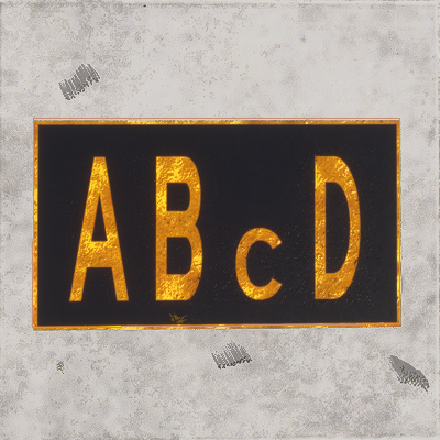 |
** |
All subsequent letters will be half height until For example: A**BCD |
 |
[,[[,[[[ |
Roman numerals for 1, 2, and 3. |  |
< |
Left Arrow |  |
^ |
Up Arrow |  |
> |
Right Arrow |  |
! |
Down Arrow |  |
^< |
Up-Left Arrow | 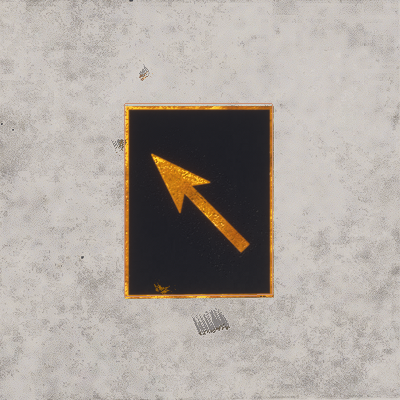 |
^> |
Up-Right Arrow |  |
!< |
Down-Left Arrow |  |
!> |
Down-Right Arrow |  |
/\.,-'# |
Special Characters |  |
$ |
New line. |
 |
<ColorText />
This is a self-closing sub-element of <TextMarking> and is used to set the colour of the text within the text marking object. This element must be included to set the text colour, and has the following attributes:
| Attribute | Description | Type | Required |
|---|---|---|---|
red |
The red component of the text colour, expressed as a value between 0 and 255. | Integer | Yes |
green |
The green component of the text colour, expressed as a value between 0 and 255. | ||
blue |
The blue component of the text colour, expressed as a value between 0 and 255. | ||
alpha |
The alpha component of the text colour, expressed as a value between 0 and 255. | No | |
override |
This is an internal parameter used by the Scenery Editor and should not be edited or added manually. | Bool | No |
<ColorBackground />
This is an optional, self-closing, sub-element of <TextMarking> and is used to set the colour of the text marking background. The element has the following attributes:
| Attribute | Description | Type | Required |
|---|---|---|---|
red |
The red component of the text background colour, expressed as a value between 0 and 255. | Integer | Yes |
green |
The green component of the text background colour, expressed as a value between 0 and 255. | ||
blue |
The blue component of the text background colour, expressed as a value between 0 and 255. | ||
alpha |
The alpha component of the text background colour, expressed as a value between 0 and 255. | No | |
override |
This is an internal parameter used by the Scenery Editor and should not be edited or added manually. | Bool | No |
<ColorOutline />
This is an optional, self-closing, sub-element of <TextMarking> and is used to set the colour of the text marking outline. The element has the following attributes:
| Attribute | Description | Type | Required |
|---|---|---|---|
red |
The red component of the text outline colour, expressed as a value between 0 and 255. | Integer | Yes |
green |
The green component of the text outline colour, expressed as a value between 0 and 255. | ||
blue |
The blue component of the text outline colour, expressed as a value between 0 and 255. | ||
alpha |
The alpha component of the text outline colour, expressed as a value between 0 and 255. | No | |
override |
This is an internal parameter used by the Scenery Editor and should not be edited or added manually. | Bool | No |
<Waypoint>
This a sub-element of both the <Airport> and <FSData> elements and is used to add a waypoint to the airport facility database or to the world.
NOTE: Editing Waypoint data may prevent the simulation performing further automatic updates to the navigation data for the airport. Please see the following section for more information: Note On Navigation Data
This element may contain the optional sub-element <Route>, but if it has no sub-elements it can be self-closing. The element has the following attributes:
| Attribute | Description | Type | Required |
|---|---|---|---|
lat |
Latitude of the waypoint, in degrees between -90.0° and 90.0°. |
Float |
No |
lon |
Longitude of the waypoint, in degrees between -180.0° and 180.0°. | Float | No |
waypointType |
The type of waypoint. |
Enum: |
No |
waypointRegion |
The waypoint region code (maximum 3 characters, based on iso-3166-2). | String | No |
waypointIdent |
The identity for this waypoint, with a maximum of five characters. | String | No |
magvar |
Magnetic variation, the angle difference between the magnetic north and true north. Negative for value to the east and positive for value to the west, measured in degrees between -360.0° and 360.0°. | Float | No |
<Route>
This sub-element of <Waypoint> is used to add a route designation to a waypoint. The element has two sub-elements - <Previous /> and <Next /> - and has the following attributes:
| Attribute | Description | Type | Required |
|---|---|---|---|
routeType |
Latitude of the airport reference point, in degrees between -90.0° and 90.0°. |
Enum:
|
No |
name |
The name of the route (maximum 8 characters). | String | No |
<Previous />
This is a sub-element of <Route> and adds the previous waypoint data to the route. This is a self-closing element with the following attributes:
| Attribute | Description | Type | Required |
|---|---|---|---|
waypointRegion |
The waypoint region code (maximum 3 characters, based on iso-3166-2). | String | No |
waypointIdent |
The identity for this waypoint, with a maximum of five characters. | String | No |
waypointType |
The type of waypoint. |
Enum: |
No |
altitudeMinimum |
The minimum altitude for the waypoint, in ft. | Float | No |
<Next />
This is a sub-element of <Route> and adds the next waypoint data to the route. This is a self-closing element with the following attributes:
| Attribute | Description | Type | Required |
|---|---|---|---|
waypointRegion |
The waypoint region code (maximum 3 characters, based on iso-3166-2). | String | No |
waypointIdent |
The identity for this waypoint, with a maximum of five characters. | String | No |
waypointType |
The type of waypoint. |
Enum: |
No |
altitudeMinimum |
The minimum altitude for the waypoint, in ft. | Float | No |
<Helipad>
This a sub-element of the <Airport> element and can be used to define one or more helipads within an airport facility.
NOTE: If you wish the helipad to be available as a starting location for helicopter flights, then you also need to define a <Start /> element of the type "HELIPAD".
This element can have the <Coloration /> sub-element, otherwise it is self-closing and has the following attributes:
| Attribute | Description | Type | Required |
|---|---|---|---|
|
|
The display name for the object in the Scenery Editor. NOTE: this is only used for ordering in the The Scenery Contents List |
String | No |
|
|
The ID of the parent group this object belongs to. NOTE: this is only used for ordering in the The Scenery Contents List |
Integer | No |
|
|
The group index of the object. NOTE: this is only used for ordering in the The Scenery Contents List |
Integer | No |
lat |
Latitude of the helipad, in degrees between -90.0° and 90.0°. |
Float |
Yes |
lon |
Longitude of the helipad, in degrees between -180.0° and 180.0°. | Float | Yes |
alt |
Altitude of the helipad, in meters. You may add the "F" suffix to convert the value to feet, for example: "13.0F". |
Float |
Yes |
alt_type |
This is used to determine the referential for the alt field |
Enum:
|
No |
surface |
Surface material to apply to the helipad |
String: "ASPHALT" |
Yes |
heading |
Facing angle for the helipad. Value between 0° and 360°. | Float | Yes |
length |
Length of the helipad. Length is in meters, but you can suffix the value with "F" for feet, eg: "2000F". | Float | Yes |
width |
Width of the helipad. Length is in meters, but you can suffix the value with "F" for feet, eg: "2000F". Float Yes | Float | Yes |
type |
The type of helipad. Note that if you enter type as CIRCLE or SQUARE and the length and width are not identical, then the shape of the helipad will be an ellipse or rectangle, respectively. |
Enum:
|
Yes |
closed |
Boolean indicating whether the helipad is closed (TRUE) or not (FALSE) | Boolean | No |
transparent |
Boolean indicating that the helipad should be drawn without pavement (markings only) | Boolean | No |
|
|
This attribute will add a Final Approach and Takeoff (FATO) area to the helipad of the given length, in meteres. |
Float | No |
|
|
This attribute will add a Final Approach and Takeoff (FATO) area to the helipad of the given width, in meteres. |
Float | No |
|
|
This attribute tells the simulation to display the FATO area markings for a runway when set to "TRUE". |
Boolean | No |
|
|
This attribute, when included in the XML will display the given value as a runway number within the Final Approach and Takeoff (FATO) markings. |
Integer | No |
|
|
This attribute, when set to "TRUE", will prefix the runway numbers 1 - 9 with a 0, as done in European airports. |
Boolean | No |
excludeVegetationAround |
This attribute, when set to "TRUE", will remove any vegeation around the helipad area. |
Boolean | No |
excludeBuildings |
This attribute, when set to "TRUE", will prevent all generated buildings from being spawned in the helipad area. | Boolean | No |
|
|
This is the index of the Apron Controller to be assigned to this taxiway stand service location. IMPORTANT! This index value cannot be set in the XML and is assigned by the The Scenery Editor when you assign an Apron Control to a helipad. |
Integer | No |
<Start />
This a sub-element of the <Airport> element and is used to designate one or more helipads in the airport to be used as possible start locations for a flight. Note there should be at least one <Start> element defined for each <Helipad> element.
IMPORTANT! In previous versions of the simulation this was parsed for both Runways and Helipads. However that is no longer the case and this element only applies to helipads, while runways should use the dedicated <RunwayStart /> element instead. Airports created in previous versions will have this element automatically updated to a runway start element on import, if the type parameter flags it as such.
This is a self-closing element and has the following attributes:
| Attribute | Description | Type | Required |
|---|---|---|---|
number |
Number of the runway to start on. Note that you do not suffix the designator onto this value, but instead define it separately in the designator attribute. |
Integer |
No |
designator |
Designator of the runway chosen to start on. NOTE: This is a legacy attribute and only used by airports created in previous versions of the simulation. |
Enum:
|
No |
lat |
Latitude of the start position, in degrees between -90.0° and 90.0°. |
Float |
Yes |
lon |
Longitude of the start position, in degrees between -180.0° and 180.0°. | Float | Yes |
alt |
Altitude of the start position, in meters. You may add the "F" suffix to convert the value to feet, for example: "13.0F". |
Float |
Yes |
alt_type |
This is used to determine the referential for the alt field |
Enum:
|
No |
heading |
Facing angle for the start position. Value between 0° and 360°. | Float | Yes |
type |
Type of start point. Can only be HELIPAD, as the other possible values are deprecated. |
Enum:
|
No |
<Jetway>
Jetway elements are part of an <Airport> element, and must contain a single <SceneryObject> element. One jetway can service at most one parking spot. A jetway will be animated and will usually come in to the main exit on the left side of the aircraft. AI controlled aircraft will also trigger the animation of the jetway. To replace jetways at an airport, use the <DeleteAirport> element with the <deleteAllJetways> field set to "TRUE", then enter the new jetway elements. Note that all parking spots do not require jetways.
The available attributes for jetways are as follows:
| Attribute | Description | Type | Required |
|---|---|---|---|
|
|
The display name for the object in the Scenery Editor. NOTE: this is only used for ordering in the The Scenery Contents List |
String | No |
|
|
The ID of the parent group this object belongs to. NOTE: this is only used for ordering in the The Scenery Contents List |
Integer | No |
|
|
The group index of the object. NOTE: this is only used for ordering in the The Scenery Contents List |
Integer | No |
gateName |
Gate or parking spot name. All Jetways require a name and a |
Enum: DOCK |
Yes |
parkingNumber |
The number for the parking spot. All Jetways require a number and a |
String | Yes |
suffix |
Suffix to be added to the jetway parking name and number. |
Enum: GATE_A |
No |
<VDGS>
A VDGS object is part of an <Airport> element, and is used to add a Visual Docking Guidance System to a stand at an airport. This element requires the <SceneryObject> sub-element to define the scenery object to use as the VDGS, and also requires the following attributes:
| Attribute | Description | Type | Required |
|---|---|---|---|
|
|
The display name for the object in the Scenery Editor. NOTE: this is only used for ordering in the The Scenery Contents List |
String | No |
|
|
The ID of the parent group this object belongs to. NOTE: this is only used for ordering in the The Scenery Contents List |
Integer | No |
|
|
The group index of the object. NOTE: this is only used for ordering in the The Scenery Contents List |
Integer | No |
gateName |
Gate or parking spot name. All VDGS require a name and a |
Enum: DOCK |
Yes |
parkingNumber |
The number for the parking spot. All VDGS require a number and a |
String | Yes |
suffix |
Suffix to be added to the VDGS parking name and number. |
Enum: GATE_A |
No |
<BlastFence>
<BoundaryFence>
These are both sub-elements of the <Airport> element and are used to define a blast and boundary fences. Both elements require at least two <Vertex /> sub-elements to define the points between which instances of the given model will be placed, as well as a <Model /> sub-element to define the model that is used.
They also have the following attributes:
| Attribute | Description | Type | Required |
|---|---|---|---|
|
|
The display name for the object in the Scenery Editor. NOTE: this is only used for ordering in the The Scenery Contents List |
String | No |
|
|
The ID of the parent group this object belongs to. NOTE: this is only used for ordering in the The Scenery Contents List |
Integer | No |
|
|
The group index of the object. NOTE: this is only used for ordering in the The Scenery Contents List |
Integer | No |
profile |
This is the GUID of the model that will be used to populate the blast fence. |
String |
No |
snapToVertices |
When this attribute is set to "TRUE" the chosen model will only be placed on the single vertices (points) that make up the blast fence, instead of being placed along the lengths of the paths. Default value is "FALSE". | Bool | No |
spacing |
This sets the spacing (in meters) between the models as they are placed along the blast fence. This set to a value that brings the object models closer together to keep continuity between them. | Float | No |
heading |
This attribute can be used to modify the orientation (heading) of the model by a value in degrees. This will be a relative orientation if the rotation attribute is set to "Follow edge" or "Random", and an absolute orientation if the attribute is "Same". |
String | No |
scale |
This attribute is used to scale the model up or down. The base value is 1, and a value less than one will scale it down and a value greater than 1 will scale it up. This will also be cumulative with the scale applied if the scaleDelta option is greater than 0. |
Float | No |
scaleDelta |
This attribute will add a random variation in scale to each model placed along the blast fence. The default value is 0, which is no random variation, and any value greater than 0 will be used to apply a random variation in size to each model using the given value as a magnitude for the variation. This variation will be cumulative with the scale setting. |
Float | No |
rotation |
With this attribute you can change the way the model rotation will be handled by the simulation. It can be one of the following strings:
|
String | No |
avoidDiscontinuity |
This attribute can be set to "TRUE" to have the scenery editor try and ensure that the models used match up correctly at the corners of the vector path. If set to "FALSE" then the model may overrun the length of the vectors. | Bool | No |
adjustScalingAlongPath |
Adjusts the model scale along the path to fit the available space. | Bool | No |
castShadow |
If this attribute is set to "TRUE" the models used will cast a shadow, and if set to "FALSE" they won't. | Bool | No |
forcedAltitude |
If this attribute is set to "TRUE", it will force the vector placement models to be snapped to the altitude of the object, rather than the ground. | Float | No |
<DeleteAirport>
This a sub-element of the <Airport> element and is used to remove certain features from the area the airport occupies. Since most of the airports that are going to be edited are preexisting airports within the simulator, it is important to understand the behavior behind the <DeleteAirport> structure: when loading two packages that cover the same airport, the simulator will load both versions of the airport from each package, adding the data from each package together, rather than overriding one package with another. In the case that this is not what you want, you need to use this element to remove features from any previously loaded airport (including those that are defined as part of the base sim).
This element can have the following attributes:
| Attribute | Description | Type | Required |
|---|---|---|---|
deleteAllApproaches |
Remove all data coming from <Approach> fields |
Boolean | No |
deleteAllApronLights |
Remove all data coming from <ApronEdgeLights> field |
Boolean | No |
deleteAllAprons |
Remove all data coming from <Aprons> field |
Boolean | No |
deleteAllArrivals |
Remove all data coming from <Arrival> fields |
Boolean | No |
deleteAllBlastFences |
Remove all data coming from <BlastFence> fields |
Boolean | No |
deleteAllBoundaryFences |
Remove all data coming from <BoundaryFence> fields |
Boolean | No |
deleteAllControlTowers |
Remove all data coming from <Tower> fields |
Boolean | No |
deleteAllDepartures |
Remove all data coming from <Departure> fields |
Boolean | No |
deleteAllFrequencies |
Remove all data coming from <Com> fields |
Boolean | No |
deleteAllHelipads |
Remove all data coming from <Helipad> field |
Boolean | No |
deleteAllILSs |
Remove all data coming from <ILs> fields |
Boolean | No |
deleteAllJetways |
Remove all data coming from <Jetway> fields |
Boolean | No |
deleteAllLightSupports |
Remove all data coming from <LightSupport> fields |
Boolean | No |
deleteAllPaintedElements |
Remove all data coming from <PaintedElements> fields |
Boolean | No |
deleteAllProjectedMeshes |
Remove all data coming from <ProjectedMesh> fields |
Boolean | No |
deleteAllRunways |
Remove all data coming from <Runway> field |
Boolean | No |
deleteAllStarts |
Remove all data coming from <Start> field |
Boolean | No |
deleteAllTaxiways |
Remove all data coming from <TaxiwayPoint>, <TaxiwayParking>, <TaxiwayPath> and <TaxiwayName>fields |
Boolean | No |
deleteAllTaxiwaySigns |
Remove all data coming from <TaxiwaySign> fields |
Boolean | No |
deleteAllTerminalNDBs |
Remove all data coming from <Ndb> fields |
Boolean | No |
deleteAllTerminalWaypoints |
Remove all data coming from <Waypoint> fields |
Boolean | No |
deleteAllVectorPlacement |
Remove all data coming from <VectorPlacement> fields |
Boolean | No |
In addition to these attributes, there exists the following sub-elements which can be contained within the <DeleteAirport> structure in order to have a more refined deletion of certain objects.
<DeleteRunway />
The purpose of the <DeleteRunway /> element is to delete a specific runway from an airport. Note that this is a self-closing element and has the following attributes:
| Attribute | Description | Type | Required |
|---|---|---|---|
surface |
GUID or Name of the surface of the runway to delete | GUID or String | Yes |
number |
Number of the runway to delete. Note that you do not suffix the designator onto this value, but instead define it separately in the designator attribute. |
Integer:
or Enum: EAST |
Yes |
designator |
Designator of the runway to delete |
Enum: NONE |
No |
<DeleteStart />
The purpose of the <DeleteStart /> element is to delete a start location from an airport. This element is available but rarely required. Note that this is a self-closing element and has the following attributes:
| Attribute | Description | Type | Required |
|---|---|---|---|
type |
Type of start to delete |
ENUM:
|
Yes |
number |
Number of the runway where the start is found |
Integer:
or Enum: EAST |
Yes |
designator |
Designator of the runway where the start is found |
Enum: NONE |
No |
<DeleteFrequency />
The purpose of the <DeleteFrequency /> element is to delete specific navigation data related to the airport. Note that this is a self-closing element and has the following attributes:
| Attribute | Description | Type | Required |
|---|---|---|---|
frequency |
The frequency in hertz to be removed. | Float | Yes |
type |
The type of navigation freuqncy to be removed. |
Enum: APPROACH |
Yes |
<HoldingPattern>
This is a sub-element of the <Airport> element, and is used to define a holding pattern. It has no sub-elements and takes the following attributes:
| Attribute | Description | Type | Required |
|---|---|---|---|
name |
The common name of the holding pattern. | String | No |
fixType |
The type of fix for the holding pattern. |
Enum: |
Yes |
fixRegion |
The fix region code (maximum 3 characters, based on iso-3166-2). | String | Yes |
fixIdent |
The fix identity (maximum 5 characters). |
String |
No |
inboundHoldingCourse |
Float | No | |
turnDirection |
Turn direction supplied for this holding pattern, which can be L (Left), R (Right) or E (Either), where the default is E. |
Enum:
|
Yes |
length |
The length of the holding pattern, in meters. You may suffix the value with "N" to get nautical miles, eg: "34N". If used, then do not enter a value for time. |
Float | No |
time |
Time, in minutes. If used, then do not enter a value for length. |
Float | No |
altitudeMinimum |
The minimum altitude, in ft, for the holding pattern. | Float | No |
altitudeMaximum |
The maximum altitude, in ft, for the holding pattern. | Float | No |
holdSpeed |
The speed of the aircraft when using the holding pattern. | Float | No |
requiredNavigationPerformance |
Float | No | |
arcRadius |
The arc radius for the holding pattern, in degrees. | Float | No |
<WasmModule />
This is a sub-element of the <Airport> element and is used to add a Web Assembly module (WASM) to an airport. This is a self closing element and has the following attribute:
| Attribute | Description | Type | Required |
|---|---|---|---|
path |
This is the path to the WASM that you want the airport to use, relative to the root folder of the package. |
String |
Yes |
For more information please see the following section:
Related Topics