CREATING A CHECKLIST
Although a checklist can be created from scratch by manually creating and writing all the different XML files - which is a valid approach and can lead to a suitable result - on this page we are going to present what we consider an "optimal" workflow for the checklist creation, and one that was used in the creation of the aircraft for Microsoft Flight Simulator 2024. This recommended approach offers two main advantages over manually creating the checklist files:
- One is that it will make use of the available localized texts of the file
Checklist.locincluded as part of the simulation installation. So, if a text you want to display is already available inChecklist.loc, the generated XML will make a call to this text entry, and automatically localize it for you. - The other is that it will help you create any missing entries and add them into the
aircraft.locfile of your own aircraft package.
NOTE: For more information on localization, please see here: Localization (LOC Files)
The general production flow for creating the checklists using this recommended method is as follows:
- Fill in an Excel file with the checklist texts and the levels of detail (a pre-setup Excel Integrator file is supplied with the SDK and explained below)
- Import missing text into the
aircraft.locfile of your own aircraft package with the help of MSFS Localization Manager. - Create and populate the aircraft XML files with the data provided by the Excel file.
- Test the output in the simulation.
- Add appropriate visual helpers.
- Test the final output in the simulation.
The rest of this tutorial will refer to the Integrator Excel File, since this file is essential to the recommended checklist creation workflow. You can download the file and find more information about it from the following page:
Before continuing, you need to create a copy of the Integrator Excel file so as not to edit the original version and ensure your checkpoints are generated correctly for the aircraft. When creating the copy, it is important to understand that the name of the file will be used as part of the automatic generation of checkpoint names, so you should name the file with something that identifies the aircraft you are working on, for example: DA62_Checklist_Integrator.xls.
The Integrator Tracking Tab
Having created your copy of the integrator file, you should open it for editing. The first thing that you will have to do is fill in the Integrator Tracking tab and then fill in all the text information that will be part of the checklist: page, block, subject, expectation and - depending on the checkpoint - clue:
![]()
While filling this in, you may notice that some cells will be coloured. This is done to show that there is some issue with the text input:
-
Yellow (Columns B - F)
If a cell is colored yellow, it means that the text begins or ends with a space " " , has a double space " ", or contains a return character. To fix this issue, delete all useless space " " characters and make sure there are no line returns in the text.
-
Orange (Columns B - F)
If a cell is colored orange, it means that the number of characters inside the cell is above the Excel limitations of the formulas used in the integrator. These cells will have to be treated manually (as mentioned here: Known Limitations).
-
Red (Columns E or G)
If a cell is colored red in column E, it means you have not filled in an Expectation for a given subject, which is a mandatory requirement (all subjects must have an expectation). If a cell is colored red in column G, it means that the Level of Detail is missing. This is easily resolved by selecting a level of detail from the drop-down list.
NOTE: The level of detail setting "PRO" corresponds to the EFB option "EXPERT".
The Checklist.loc DATA Tab
Once you have the data added into the Integrator Tracking tab, you should check the Checklist.loc DATA tab. On this page you will immediately see if there are any checklist issues they will be flagged in orange, and a message will be shown to explain the issue. If you see any problems, go back to the Integrator Tracking tab and fix them.
Adding The New Text To The Aircraft.loc File
To add the new checklist text you've created into the localisation file for your aircraft, you will need to do either:
- If you do not already have an
aircraft.locfile, create a new<aircraft>.locprojfile in the MSFS Localization Manager ( see Getting Started for information on how to do this). - If you have already created a
*.locprojfile and have an aircraft.loc file, then this should be opened in the localisation manager so it can be updated from the checklist integrator Excel file..
Once you have the project file open, please follow these steps:
- From the top menus of the MSFS Localization Manager, click on Import, and select Import Excel File:
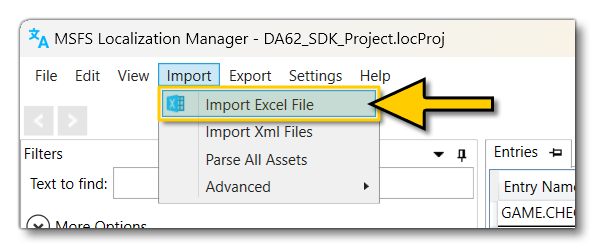 Browse to where you have saved the Checklist Integrator file you have been working on and select it to load it into the localisation manager.
- In the Import window, make sure to change the Import Mode to Target Localization File:
 Note that you may get an error saying that the source file is Read Only. If this happens you can simply click on the
 OKbutton (this usually happens because you have the file open for editing when you try to import it).
- Set the Target Package option to the aircraft package, and set the Target Localisation File option to "aircraft":
 If you do not see an aircraft file in the Target Package drop-down, then you will have to generate the
 *.locprojfor the aircraft, as explained here.
- Once you have setup the data given above, you can click on the
Importbottom. All texts and their entry names from the Excel will be imported into the Localisation Manager, and a summary will be displayed. You can clickOKto continue.
- Finally, press
Ctrl+Sin the main window of the Localisation Manager to save the new entries to the project file.
Following these steps you will have updated (and/or created) the aircraft.loc file with the checkpoint data from the Excel file, and you only need to do this once, unless you update the Excel file, in which case you should repeat the process outlined here.
Creating The Checkpoint Library File
At this point you can go ahead and use the Excel file to create the checkpoint library XML file (see Prepare Base XML for more information on this file). For this you simply need to copy the information from the C4 cell of the Library.xml tab in the excel and then paste it into the Library.xml file, which should be located in a checklist folder within the aircraft project structure (normally in the common folder).
IMPORTANT! Due to an issue with the way that Excel works, if you paste the contents of the cell directly into an XML file in - for example - Notepad++, then you will find that quotes are duplicated. To avoid this, you may have to first paste the text into a Microsoft Word document, then copy that into the XML file.
There should be no further work required on this file for now as the Excel sheet should have generated it correctly to "just work" with localisation and the checklist system.
Creating The Checklist File
The checklist file can also be created from the Excel file (see Prepare Base XML for more information on the checklist file). This is done by copying the A4 cell on the Checklist.xml tab in the Excel sheet, which represents the structure of the XML file, with all the required <Step> elements (all steps are mandatory - a step can be empty with no page inside, but it cannot be missing). This can then be pasted into the <Aircraft>_Checklist.xml file, which should be located in a checklist folder within the aircraft project structure (normally in the common folder).
IMPORTANT! Due to an issue with the way that Excel works, if you paste the contents of a cell directly into an XML file in - for example - Notepad++, then you will find that quotes are duplicated. To avoid this, you may have to first paste the text into a Microsoft Word document, then copy that into the XML file. Please keep this in mind for the rest of this document when it references copy/pasting text from the Excel file.
Having created this file and copied all the data from the Excel file, you may want to "prettify" the output to ensure that it's correctly formatted before continuing (for example, in Notepad++ this is done with Ctrl+Alt+Shift+B, and there are online tools that can do this too). Once the file is ready, you should follow these next steps exactly:
- Going back to the Excel file, you can now copy the filled cells from the B column starting with cell B4. The cells in this column contain all of the
<Page>elements of the checklist. This should be pasted into the checklist file, at the bottom, after everything else, since some reorganisation will be required.
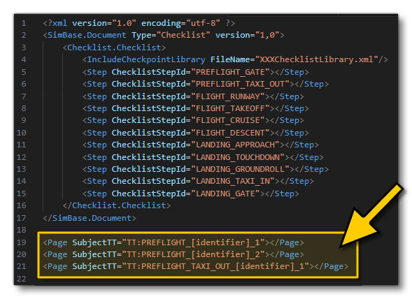
- With the page output in the checklist file, you can now go ahead and organise them into the correct steps, using the Excel file as a reference. For example, in the image above two pages need to be moved into the
PREFLIGHT_GATEstep and one into thePREFLIGHT_TAXI_OUTstep, so the final file will have something like this:<?xml version="1.0" encoding="utf-8" ?> <SimBase.Document Type="Checklist" version="1,0"> <Checklist.Checklist> <IncludeCheckpointLibrary FileName="Library.xml"/> <Step ChecklistStepId="PREFLIGHT_GATE"> <Page SubjectTT="TT:PREFLIGHT_[identifier]_1"></Page> <Page SubjectTT="TT:PREFLIGHT_[identifier]_2"></Page> </Step> <Step ChecklistStepId="PREFLIGHT_TAXI_OUT"> <Page SubjectTT="TT:PREFLIGHT_TAXI_OUT_[identifier]_1"></Page> </Step> <Step ChecklistStepId="FLIGHT_RUNWAY"></Step> <Step ChecklistStepId="FLIGHT_TAKEOFF"></Step> <Step ChecklistStepId="FLIGHT_CRUISE"></Step> <Step ChecklistStepId="FLIGHT_DESCENT"></Step> <Step ChecklistStepId="LANDING_APPROACH"></Step> <Step ChecklistStepId="LANDING_TOUCHDOWN"></Step> <Step ChecklistStepId="LANDING GROUNDROLL"></Step> <Step ChecklistStepId="LANDING_TAXI_IN"></Step> <Step ChecklistStepId="LANDING_GATE"></Step> </Checklist.Checklist> </SimBase.Document> - Having added all the pages into the relevant steps, it's time to add the various
<Block>elements (if used). Once again, these can be copied from the Excel file - from the C column starting with cell C4 - and pasted into the checklist file at the bottom before being rearranged into their correct position in the XML, for example, here is the XML after pasting the blocks at the bottom:
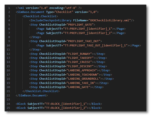 After moving the blocks the file will look something like this:
<?xml version="1.0" encoding="utf-8" ?> <SimBase.Document Type="Checklist" version="1,0"> <Checklist.Checklist> <IncludeCheckpointLibrary FileName="Library.xml"/> <Step ChecklistStepId="PREFLIGHT_GATE"> <Page SubjectTT="TT:PREFLIGHT_[identifier]_1"> <Block SubjectTT="TT:Block_[Identifier]_1></block </Page> <Page SubjectTT="TT:PREFLIGHT_[identifier]_2"> <Block SubjectTT="TT:Block_[Identifier]_2></block </Page> </Step> <Step ChecklistStepId="PREFLIGHT_TAXI_OUT"> <Page SubjectTT="TT:PREFLIGHT_TAXI_OUT_[identifier]_1"></Page> </Step> <Step ChecklistStepId="FLIGHT_RUNWAY"></Step> <Step ChecklistStepId="FLIGHT_TAKEOFF"></Step> <Step ChecklistStepId="FLIGHT_CRUISE"></Step> <Step ChecklistStepId="FLIGHT_DESCENT"></Step> <Step ChecklistStepId="LANDING_APPROACH"></Step> <Step ChecklistStepId="LANDING_TOUCHDOWN"></Step> <Step ChecklistStepId="LANDING GROUNDROLL"></Step> <Step ChecklistStepId="LANDING_TAXI_IN"></Step> <Step ChecklistStepId="LANDING_GATE"></Step> </Checklist.Checklist> </SimBase.Document> - The final step of this part of the process is to add in all the checkpoint references for each page (and block). These have been generated in the Excel file too, on the Checklist.xml sheet, in column D starting at D4. As before, copy / paste them into the XML file at the bottom:
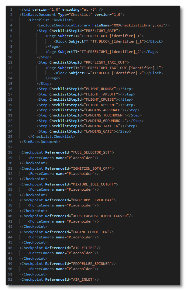 As before, these will need to be placed into the appropriate positions within the XML, eg:
<?xml version="1.0" encoding="utf-8" ?> <SimBase.Document Type="Checklist" version="1,0"> <Checklist.Checklist> <IncludeCheckpointLibrary FileName="Library.xml"/> <Step ChecklistStepId="PREFLIGHT_GATE"> <Page SubjectTT="TT:PREFLIGHT_[identifier]_1"> <Block SubjectTT="TT:BLOCK_[Identifier]_1"> <Checkpoint ReferenceId="FUEL_SELECTOR_SET" LevelOfDetail="STANDARD"> <ForceCamera name="Placeholder"/> </Checkpoint> <Checkpoint ReferenceId="MIXTURE_IDLE_CUTOFF" LevelOfDetail="STANDARD"> <ForceCamera name="Placeholder"/> </Checkpoint> </Block> <Checkpoint ReferenceId="IGNITION_BOTH_OFF" LevelOfDetail="STANDARD"> <ForceCamera name="Placeholder"/> </Checkpoint> </Page> <Page SubjectTT="TT:PREFLIGHT_[identifier]_2"> <Checkpoint ReferenceId="PROP_RPM_LEVER_MAX" LevelOfDetail="STANDARD"> <ForceCamera name="Placeholder"/> </Checkpoint> <Checkpoint ReferenceId="EXHAUST_RIGHT_LOUVER" LevelOfDetail="ADVANCED"> <ForceCamera name="Placeholder"/> </Checkpoint> <Checkpoint ReferenceId="ENGINE_CONDITION" LevelOfDetail="STANDARD"> <ForceCamera name="Placeholder"/> </Checkpoint> </Page> </Step> <Step ChecklistStepId="PREFLIGHT_TAXI_OUT"> <Page SubjectTT="TT:PREFLIGHT_TAXI_OUT_[identifier]_1"> <Block SubjectTT="TT:BLOCK_[Identifier]_2"> <Checkpoint ReferenceId="AIR_FILTER" LevelOfDetail="ADVANCED"> <ForceCamera name="Placeholder"/> </Checkpoint> <Checkpoint ReferenceId="PROPELLER_SPINNER" LevelOfDetail="ADVANCED"> <ForceCamera name="Placeholder"/> </Checkpoint> </Block> <Checkpoint ReferenceId="AIR_INLET" LevelOfDetail="STANDARD" /> </Page> </Step> <Step ChecklistStepId="FLIGHT_RUNWAY"></Step> <Step ChecklistStepId="FLIGHT_TAKEOFF"></Step> <Step ChecklistStepId="FLIGHT_CRUISE"></Step> <Step ChecklistStepId="FLIGHT_DESCENT"></Step> <Step ChecklistStepId="LANDING_APPROACH"></Step> <Step ChecklistStepId="LANDING_TOUCHDOWN"></Step> <Step ChecklistStepId="LANDING_GROUNDROLL"></Step> <Step ChecklistStepId="LANDING_TAXI_IN"></Step> <Step ChecklistStepId="LANDING_GATE"></Step> </Checklist.Checklist> </SimBase.Document> - Save out the XML file and then in the simulation open the project in the Project Editor and do a rebuild. You can then start a flight and once in the simulation thoroughly check the checklists in the app on the EFB, comparing them with the data from the Excel file. Make any changes and repeat the process until everything is correct.
Things To Note
There are a few things to note when going through the steps outlined above to create the checkpoint libraries and checklist files:
- The formulas used in the integrator file have an Excel limitation which means that they cannot handle texts longer than 255 characters. This means that you will have texts flagged as erroneous, most commonly the "Clue" texts since they tend to be longer than the subject and expectation texts. Not only will these texts be flagged in orange, there will also be an additional message in the P column of the tab Checklist.loc DATA: "message /!\ Text too long for integration - See user guide to proceed". To resolve this issue, either:
- reduce the length of the string and recreate the XML files.
- finish the process until the end and disregard these texts. If you tried to use the XML in the simulation at this point you will get an error like "no matching result in Checklist.loc DATA". These errors can be cleared by first opening the
*.locprojfile for the project in the Localization Manager and manually adding the appropriate clue text there. When finished, you can open the Checkpoint Library XML file and correct the TT name in the appropriate checkpoint with the entry name that you manually added in Localization Manager.
- The Checklist Integrator file will automatically create
<Instrument Id=""/>elements in the library file and<ForceCamera Name=""/>elements in the checklist file. This is done in an effort to save development time when implementing highlights and cameras. However it is important to delete all unnecessary<Instrument Id=""/>and<ForceCamera Name=""/>when you will have completed the implementation of your checklist. If you do not do this, the visual helper button will appear in the EFB for checkpoints that have no highlight or camera defined.
- If, while working, you notice that the ID of the checkpoints have a strange look - ie: they do not follow the structure
<AIRCRAFT>_<SUBJECT>_<EXPECTATION>_<N>, especially for the <AIRCRAFT> part. This almost aways because another Excel file has been opened after opening the checklist integrator file. This is due to an issue with the Excel program itself, and how the file recovers the aircraft name from the file name. Due to this, we strongly recommend only having one file (the checklist integrator file) open in Excel when following the instructions given above.
Information On Checklist Steps
When it comes to the setup of the various steps, the list is fixed, and they must all be a part of the checklist XML file even if some remain empty. These steps are then grouped together into three main categories and shown to the user in the EFB when they select one of the categories. The step/category breakdown is as follows:
- Category: PREFLIGHT
- PREFLIGHT_GATE - For pages related to operations made at the parking stand before pushback.
- PREFLIGHT_PUSHBACK - For pages related to pushback operations made before taxiing out.
- PREFLIGHT_TAXI_OUT - For pages related to operations made while taxiing out until stopping at the runway waiting point.
- Category: INFLIGHT
- FLIGHT_RUNWAY - For pages related to operations made at the runway waiting point.
- FLIGHT_TAKEOFF - For pages related to take-off and initial climb.
- FLIGHT_CLIMB - For pages related to climb.
- FLIGHT_CRUISE - For pages related to cruise.
- FLIGHT_DESCENT - For pages related to descent.
- LANDING_APPROACH - For pages related to approach.
- LANDING_APPROACH_VFR - For pages related to VFR approach.
- LANDING_APPROACH_IFR - For pages related to IFR approach.
- LANDING_FINAL - For pages related to final approach.
- LANDING_TOUCHDOWN - For pages related to short final and landing.
- Category: POSTFLIGHT
- LANDING_GROUNDROLL - For pages related to operations made while evacuating the runway.
- LANDING_TAXI_IN - For pages related to operations made while taxiing to the parking stand.
- LANDING_GATE - For pages related to operations made when the aircraft is immobilized on its parking stand.
Information on Checklist Blocks
In Microsoft Flight Simulator 2024, checklist blocks have new parameters that lead to three different in-game output.
General Blocks
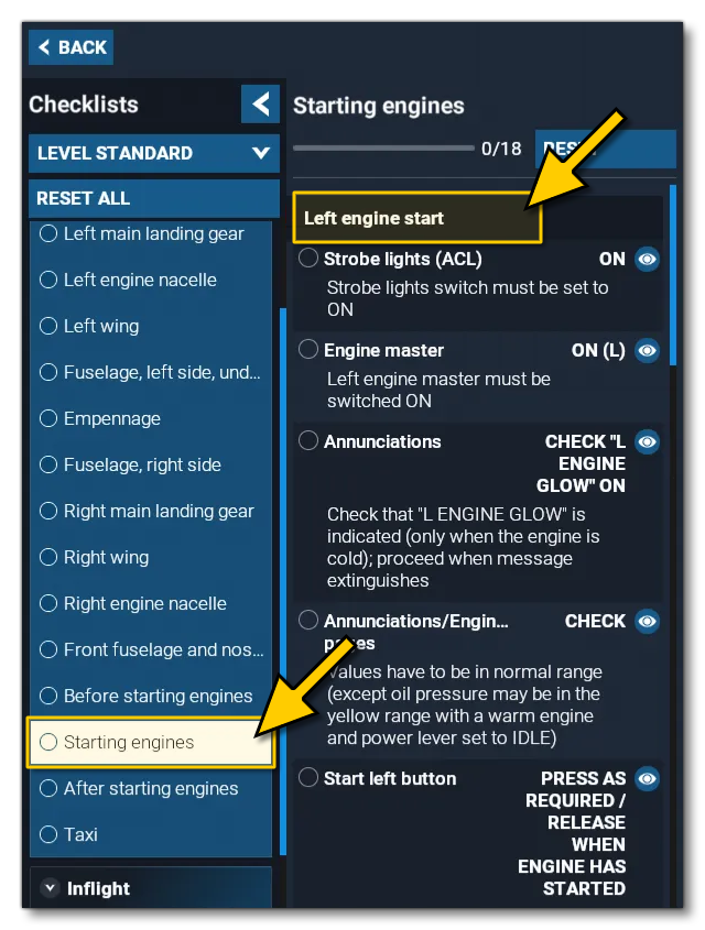
The first "type" of block is the most common one and it is used to give some general structure to the checklist. They can be considered as almost another kind of "page" to group checkpoint elements under. For example, the image below shows the DA62 block for "Left Engines Start" under the "Starting Engines" page, and in the block are various checkpoints:
This kind of block is created using the following syntax inside a <Page>. Note that all the checkpoints to be included in the block must be added inside the opening and closing block tags:
<Block SubjectTT="TT:GAME.CHECKLIST_LEFT_ENGINE_START">
    <!-- CHECKPOINTS HERE-->
</Block>
Facultative Blocks
A facultative block is - by default - not immediately visible in the EFB checklist. To show them, the user will need to go to the Settings button and then set them as active to make them appear in the current page:
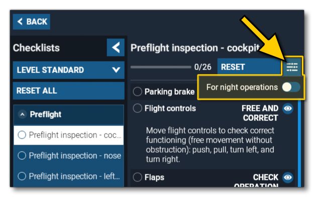
This kind of block is created using the following syntax inside a <Page>. Note that all the checkpoints to be included in the block must be added inside the opening and closing block tags, and will not be shown unless they have been made active in the EFB:
<Block SubjectTT="TT:GAME.CHECKLIST_FOR_NIGHT_OPERATIONS" Facultative="true">
    <!-- CHECKPOINTS HERE-->
</Block>
Exclusive Blocks
An exclusive block is one which contains various options, and only one of them can be chosen. The choices in this kind of block are presented as a drop-down list in the EFB, and the checkpoints displayed under these blocks will adapt to the selected choice:
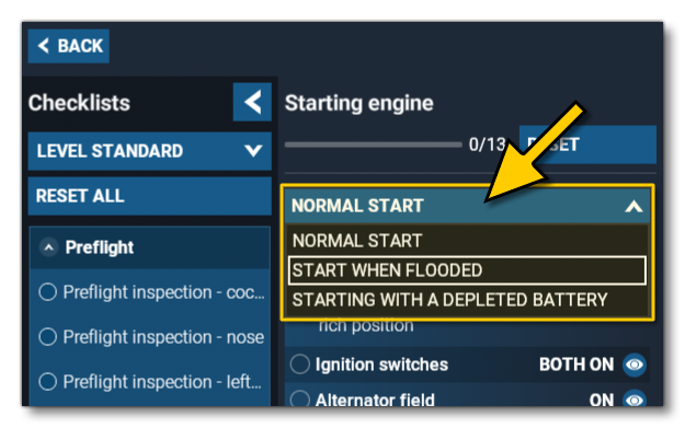
The exclusive block is created using the following syntax inside a <Page>. Note that the LinkId parameter is used to link the blocks that must be considered as exclusive to each other. Any value (numerical or a string) can be used to set the proper exclusive relation. The blocks that are part of the choice must be next to each other inside the XML file:
<!-- NORMAL_START -->
<Block SubjectTT="TT:GAME.CHECKLIST_NORMAL_START" LinkId="0">
    <!-- CHECKPOINTS HERE-->
</Block>
<!-- START_WHEN_FLOODED -->
<Block SubjectTT="TT:GAME.CHECKLIST_START_WHEN_FLOODED" LinkId="0">
    <!-- CHECKPOINTS HERE-->
</Block>
<!-- START_WITH_A_DEPLETED_BATTERY -->
<Block SubjectTT="TT:GAME.CHECKLIST_START_WITH_A_DEPLETED_BATTERY" LinkId="0">
    <!-- CHECKPOINTS HERE-->
</Block>
Additionally, inside a given page, it is possible to use the same LinkId to synchronize linked exclusive blocks to each other. Thus, in the EFB, if you select one of the block options at the beginning of the page, all blocks inside the page that have the same LinkId will be set to the selected block option, as long as the SubjectTT are the same in the two exclusive blocks, eg:
<!-- An initial exclusive-choice block -->
<Block SubjectTT="TT:GAME.CHECKLIST_NORMAL_START" LinkId="0">
    <!-- CHECKPOINTS HERE-->
</Block>
<!-- START_WHEN_FLOODED -->
<Block SubjectTT="TT:GAME.CHECKLIST_START_WHEN_FLOODED" LinkId="0">
    <!-- CHECKPOINTS HERE-->
</Block>
<!-- Some checkpoints outside of a block -->
<Checkpoint ReferenceId="MY_CHECKPOINT_1" LevelOfDetail="ADVANCED"/>
<Checkpoint ReferenceId="MY_CHECKPOINT_2" LevelOfDetail="STANDARD"/>
<!-- An another exclusive-choice block using the same LinkId and the same SubjectTT -->
<Block SubjectTT="TT:GAME.CHECKLIST_NORMAL_START" LinkId="0">
    <!-- CHECKPOINTS HERE-->
</Block>
<!-- START_WHEN_FLOODED -->
<Block SubjectTT="TT:GAME.CHECKLIST_START_WHEN_FLOODED" LinkId="0">
    <!-- CHECKPOINTS HERE-->
</Block>
In the example above, if the user chooses the EFB option "Normal start" at the top of the page, the block at the end of the page will automatically be set to "Normal start" because they share the same LinkId and the same SubjectTT.
Adding Highlights
The checklist integrator file generates a line <Instrument Id=""/> for each checkpoint of XML library file. If a Part ID is added inside the quotation marks, the node linked to the Part ID will be highlighted when the visual helpers button is pressed in the EFB (see here for more information: Helpers). Some things to note about adding these helpers are:
- It is possible to add multiple
<Instrument Id=""/>elements inside a given checkpoint to highlight all the relevant parts for the checkpoint. - While highlights can be included in the checklist XML file, in general it is recommended that you place all highlight calls into the checkpoint library file instead. This means that it will then be shared across all calls of the checklist file to a given checkpoint, keeping the code repetition to a minimum.
- All empty
<Instrument Id=""/>elements should be removed from the XML when you have finished creating the file, otherwise the EFB will display the visual helpers button even though there are no highlights defined.
Helpers For Interactive Elements
If you need to find the Part ID for some interactive element, it can easily be found using the Behaviors Debug window. For this, you will need to build your aircraft and start a flight in the simulation. Once in the flight, you can open the Behaviors Debug window and select the Inspector tab, then hover the mouse over the part you need the ID for and press Ctrl+G. This will cause the debug window to show the part ID(s) associated with the part:
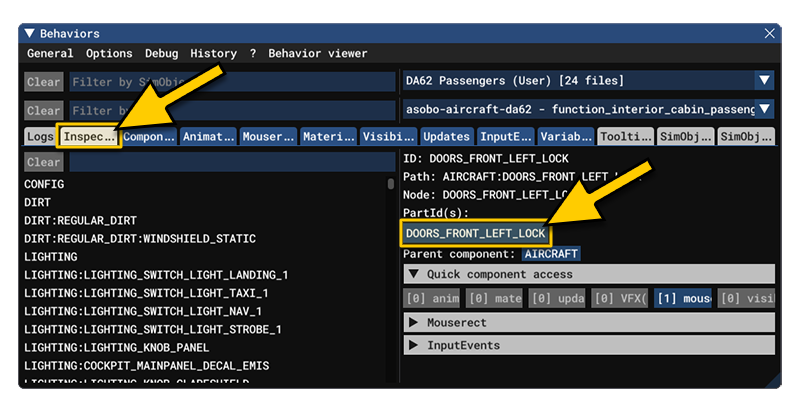
NOTE: Sometimes the Behavior Debug window will show several Part IDs for a given element. This is often becuase one of them refers to a group of nodes, meaning it will highlight elements other than the one you want. In these cases, the only thing you can do is test and see to find the one(s) you want.
Helpers For Non-Interactive Elements
To highlight elements that are not interactive - for example, the frame of a gauge instrument or a custom invisible node specifically created for highlighting purposes - you will have to define the Part ID yourself in the XML file where the behaviors are defined. The process for this is as follows:
- To start with, ensure that a node actually matches the element you want to highlight. Note that, all child nodes of the targeted node will be highlighted by the Part ID you create, so it's important to pay attention to the node architecture and make separated nodes for highlighting purposes, if necessary.
- With the Part ID you can then create a new
<Component>in the XML file of the behavior that applies to the glTF containing the node you want to highlight. This should have the following format:<Component ID="FREE_TEXT" node="NODE_TO_BE_HIGHLIGHTED"> <UseTemplate Name="ASOBO_PartId_Template"> <PART_ID>PART_ID_USED_TO_CALL_THE_HIGHLIGHT</PART_ID> </UseTemplate> </Component>
As an example we'll look at the Cabri G2. In that aircraft we want to highlight the frame around the MGB T indicator:

Since this is not an interactive part, we need to add the following into the Cabri interior behavior XML (where ELECTRICAL_INDICATOR_HIGHLIGHT_MGBT is the name of the node in the glTF):
<Component ID="MGB_TEMPERATURE_INDICATOR_HIGHLIGHT" node="ELECTRICAL_INDICATOR_HIGHLIGHT_MGBT">
    <UseTemplate Name="ASOBO_PartId_Template">
        <PART_ID>ELECTRICAL_INDICATOR_HIGHLIGHT_MGBT</PART_ID>
    </UseTemplate>
</Component>
We are now able to call the highlight with the defined Part ID, ELECTRICAL_INDICATOR_HIGHLIGHT_MGBT. In this example, we gave the same name to the Part Id as the node one.
Note that if your aircraft is using the Microsoft Flight Simulator 2020 model behaviours (not recommended) then you will need to use the the following XML instead of that given above:
<UseTemplate Name="ASOBO_GT_Highlight_Template">
    <HIGHLIGHT_NODE_ID>NODE_TO_BE_HIGHLIGHTED</HIGHLIGHT_NODE_ID>
    <PART_ID>PART_ID_USED_TO_CALL_THE_HIGHLIGHT</PART_ID>
</UseTemplate>
Helpers For HTML
It is possible to highlight an HTML <div> on in-game screens as part of a checkpoint. The syntax in the checkpoint library then looks like this:
<Instrument Id="HTML:THE_NAME_OF_THE_SCREEN:div_reference_to_highlight"/>
As an example, in the Cabri the RPM gauge on the EPM has a highlight which looks like this when used in the checklist:
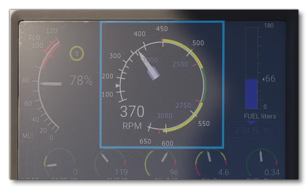
The checkpoint instrument XML for this highlight looks like this:
<Instrument Id="HTML:AS_EPM:rpm-gauge"/>If you need to find the name of the HTML element while running the simulation, you can use the Coherent GT Debugger as it lists all the screens which can then be clicked and inspected. Once you are inspecting a screen, you can click on an element in the simulation for the debugger to take you to the appropriate line in the HTML. Note that the reference of the div can be either - in order of preference - the value of the parameters "data-checklist", "id" then "class".
Cameras
The checklist integrator file generates the following line for each checkpoint of the XML checklist file:
<ForceCamera Name=""/>If the empty string "" is replaced by the name of a camera (in quotes, as set in the Title parameter for the camera), the camera will then be assigned to move to the defined point of view when the visual helpers button is pressed in the EFB. Note that you can only have one line to force the camera position inside any given checkpoint.
In general it is recommended to add the call to cameras into the checklist file itself, since - depending on the page a given checkpoint is called in - it is not always correct or justified to have the camera move. For example, moving the camera can be set aside for checklist pages dealing with a flight phase (Take Off, Landing, Cruise, etc...). This is to avoid changing the user's view while they are in a dynamic piloting phase, which risks them losing orientation and control. In these cases, having a highlight on the checklist element is considered sufficient to guide them.
You should ensure that the cameras you use are setup correctly in the cameras.cfg file and that they belong only to the following sub-categories: Pilot, Instrument or Checklist. If you want to create cameras that will only be used in the checklist context, then create them in the category Checklist so that they will not be part of the UI camera panel and will also not be accessible for bindings. The image below shows a typical checklist camera setup in the SimObject Editor:
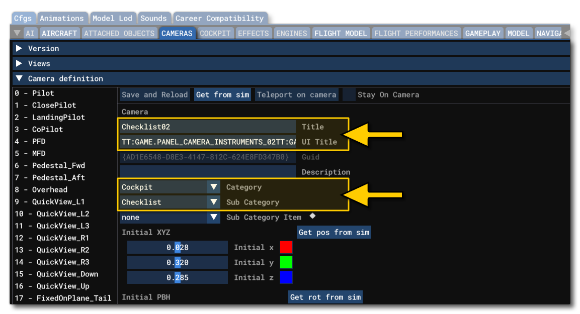
Checklists And Modular Aircraft
Checklists can make use of the Modular SimObject architecture to avoid making duplicates for the parts of a checklist that are common to several presets of any given modular aircraft. For example, the XCub has several variants - wheeled, with skis, and amphibious - and most checkpoints are common to all variants. It is therefore interesting to build the checklist as a modular checklist and implement once the common checkpoints, then add or remove the relevant / non-relevant checkpoints for any given variant.
Here is the structure we recommend for creating a modular checklist:
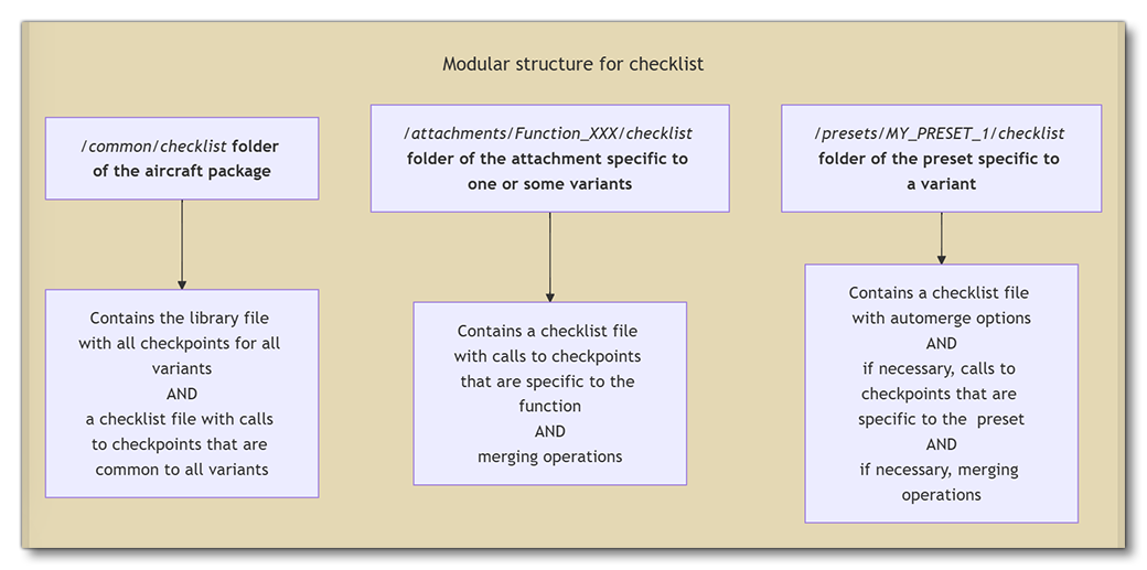
Merging operations are used to:
- move pages, blocks, checkpoints to their correct locations inside the common checklist
- remove pages, blocks, checkpoints that are not relevant for a function or a preset in the in-game displayed checklist
For a dedicated example showing how this would work please see the following page: