USING THE NAVIGATION GRAPH EDITOR
Navigation graphs are required by the various cabin services that are used by aircraft and other SimObjects, or by the different airport Apron Services. Essentially they are a way to create nodes, edges (paths), volumes, and areas of exclusion, all of which can be used by SimObjects to navigate around the aircraft or the airport. This section is for explaining the basic use of the Navigation Graph editor within the context of an Aircraft or an Airport. If you need information on all the editor features, please see here:
Adding A Navigation Graph CFG To An Aircraft
To add a navigation graph to an aircraft you should open the aircraft in The SimObject Editor and on the Navigation Graph tab, click on the + button.

Clicking this will open the following window:

Here you can give an identifier to the CFG file that is being created. This is required since you can have multiple navigation graphs per common/preset/attachment used by the SimObject. Once you have given this name and clicked on Create, the file will be shown in the editor and you can start to add nodes and edges.
Adding A Navigation Graph CFG To An Airport (WIP)
NOTE: Before getting started with the navigation graph at an airport, you will need to start a flight at the airport you wish to add the graph to. This is because (currently) the first node on the graph will be added at the aircraft position. Once you have started a flight at the required airport, you should pause the simulation, open (or create) the airport package, and then continue to add/edit the navigation graph.
Adding a navigation graph to your airport requires you to open the graph editor in The Scenery Editor. For that, go to the View menu and select the Navigation Graph Editor option:

With the editor open, you need to go to the Navigation Graph CFG Editor window, and click on the + button:
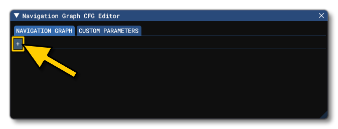
Clicking this will open the following window:

Here you can give an identifier to the CFG file that is being created. This is required since you can have multiple navigation graphs per airport. Once you have given this name and clicked on Create, the file will be shown in the editor and you can start to add nodes and edges.
Controls
The following inputs are used to add, remove, and move things within the Navigation Graph Editor:
- Right Click: Open the Context Menu which will give different options depending on where you click.
- Right Click + Drag: Right clicking (without release) and dragging will pan the Navigation Graph editor.
- Left Click: Select a node or an edge in the graph.
Ctrl+ Left Click: Select multiple nodes or edges in the graph. Selected nodes can then be clicked on and moved as a group, and selected edges can be deleted in a group using the Right Mouse button Context Menu.- Left Click + Drag: If you click on a single node and drag, this will move that node. When clicking outside a node and dragging, you will create a bounding box which can be used to select multiple nodes within the graph: clicking and dragging any of the selected nodes after this will move all of them together.
Adding A Node To A Main Graph
The most important part of a Navigation Graph is the Main Graph. This is where the core navigation components will be added:
- Nodes - This is a point in the graph where some kind of decision can be made or a task can be performed by one of the object actors (unless the node is defining an exclusion area).
- Edges - This is a "path" that connects either two nodes together, or a sub-graph to a node.
- Sub-Graphs - This is a collection of nodes, edges, sub-graphs, or exclusion areas that can be connected multiple times to the main graph.
- Exclusion Areas - This is a collection of 3 or more nodes (that form an N-sided polygon) which can be used to exclude areas of the navigation graph from use by object actors.
Adding The First Node
To add a node into the Main Graph (or a Sub Graph, as explained below), you need to Right Click in the Navigation Graph Editor and select the Add Node option:
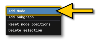
When you add a node in this way, it will be added to the graph view and look like this:
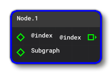
The node will have an input connection (index) and a sub-graph connection. Not shown on the node are the different parameters that define its properties. These can be edited in the The Navigation Graph Tab for the SimObject Editor or the The Navigation Graph CFG Editor (WIP) for the Scenery Editor.
To be able to edit the node position and other properties directly in the simulation (whether it's for an aircraft or for an airport) you should go to the Node section and enable The Edition Gizmo:
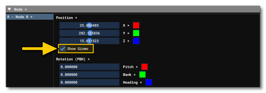
With this enabled you can then move the node directly in simulation scene, as well as edit some other properties, like volumes.
For Airports (WIP)
When adding nodes to an airport, the initial setup is the same as that given above, ie: right click then select Add Node. However, this node will be at the 0, 0, 0 position, which is not where it should be for the airport. Currently the method for setting the initial node to the desired position at your airport is as follows:
-
Set The Graph To Use World Coordinates
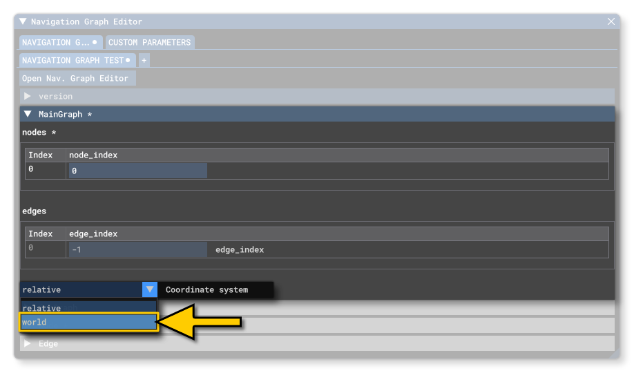
By default all nodes on the main graph will be placed at a relative position to the user aircraft SimObject. However, for airports this is not what you need and so after adding the node you need to go to the Navigation Graph CFG Editor, expand the [MainGraph.N] section, and set the Coordinate System to world:
-
Move The Node To The AIrport
With the node created and the Gizmo enabled, you can now position the node at the airport location. For that you should go to The In-Game Edition Tab and click on theSet Cur Node To Aircraft Posbutton. This will move the node to the position of the aircraft that you started the flight with before opening the airport package for editing. You can then position the node at the position you want in the airport using the Gizmo.
Editing Nodes In The Simulation
Once you have added the node, you will be able to see it in the simulation, represented as a wireframe sphere (placed at the Datum Reference Point by default for aircraft and at the 0,0,0 position in the world for scenery):

With the visual reference in the simulation, you can click on the Show Gizmo option in the SimObject Editor under the "Position" section which will then add The Edition Gizmo to the simulation. With the Gizmo you can accurately position the node within the aircraft or the airport:
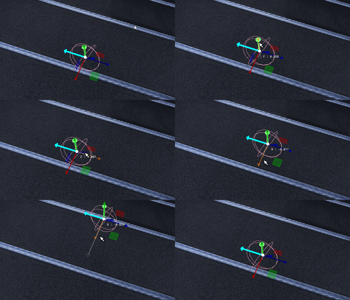
The Edition Gizmo can also be used to rotate the node, and - if the node is to symbolise a spacial volume - you can use it to set the size of this volume:

Having set up the node within the simulation, you would normally go ahead and add further nodes, as required. You can do this by using the Right Click menu and Add, or - if you wish to maintain the properties of the first node - which we recommend for editing airport nodes so you don't have to always move each one to the aircraft as you create it - you can right click on the node and select Duplicate, then edit the properties if required:

The image below shows 4 nodes that have been created in the Node Editor and how they look within the simulation:

Connecting Nodes With Edges
Once you have a series of nodes in the graph, you can then connect them with edges. This is not a requirement, but in many cases it will be what you want since the edges will be used to tell objects actors where to move and interact, depending on the mission files or apron services that are using the graph.
Adding an edge is simple within the Navigation Graph, as you just need to click on the Index output, and connect it to the Index input of another node, as shown in the animation below:

Once you connect the nodes with edges, they will be listed in the SimObject Editor/Navigation Graph CFG Editor, and you will also be able to see them visualised in the simulation (as long as the Navigation Graph Editor window is open):

The Sub Graph
A Sub Graph is like the Main Graph, in that it can contain nodes, edges and exclusion areas. Sub graphs are an ideal way to create series of repeating nodes and edges, since you can create a single sub graph and then assign it to multiple nodes in the main graph.
A good example of using a sub graph would be for a passenger airliner: you would have a single set of nodes and edges for the central aisle, and then create a sub graph with the nodes for the seat positions on either side. This sub graph would then be assigned to each of the main graph nodes.
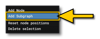
To create a sub graph, you click the Right Mouse button anywhere in the Main Graph and select Add Sub Graph:
This will add a new Sub Graph node to the Main Graph, and the sub graph will be given it's own tab in the editor:

By selecting the tab, you will be presented with a new graph where you can then add further nodes and edges, as explained above, only these will be associated with the Sub Graph rather than the Main Graph:

If you go back to the Main Graph, you can then assign the Sub Graph to one or more nodes, as shown in the image below:

The Sub Graph nodes will now also be drawn within the simulation, and you'll notice that these are coloured differently so you can see that they belong to a Sub Graph. In the Navigation Graph, the Sub Graph can be connected to as many nodes on the Main Graph as required, and in the simulation each one of those nodes will show the Sub Graph nodes:
IMPORTANT! You cannot assign a Sub Graph to a node within another Sub Graph, only to nodes in the Main Graph
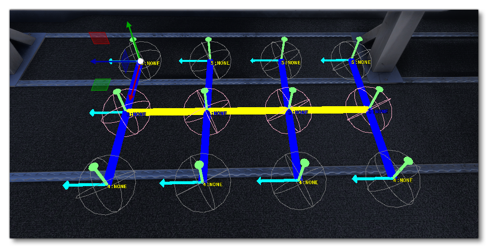
It should be noted that once you have set up the graph like this, you can then use the The Edition Gizmo on the nodes in the simulation, and when you edit a node that is part of a Sub Graph, ALL of the sub graph nodes will update to reflect this change (this applies for all Gizmo options for position, orientation and volume):

The nodes within the Sub Graph are connected to each other but they are not actually connected to the main graph. The Sub Graph has been assigned to a node, but there are no paths between the Sub Graph nodes and the node the Sub Graph has been assigned to. This may be exactly what you want, but if you require the nodes to be used for pathing or anything like that, then you need to connect them with edges to the "parent" node. This is done simply by checking the edgeToMainNode option on the nodes in the Sub Graph. The visuals in the simulation will also update to show the new edges:
