THE NAVIGATION GRAPH EDITOR
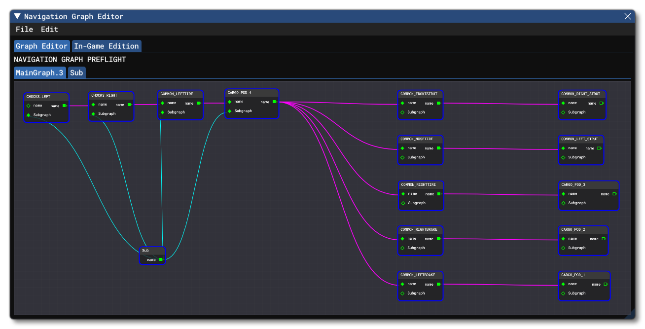
The Navigation Graph is opened from the View menu in The SimObject Editor or by the View menu of The Scenery Editor (or by clicking the Open Nav. Graph Editor button on the tab for the navigation_graph.cfg). This editor is used to define the different nodes and edges that will be used to create a navigation graph for the SimObject or Airport being defined.
The Navigation Graph gives you an easy method to edit the edge and node values and see the way that they connect, and as such it is the recommended method for creating a navigation graph for Microsoft Flight Simulator 2024.
On this page you can find information on the editor and it's sub windows and menus, but for information on how to use the editor, please see here:
Menus
The following menus are shown at the top of the Navigation Graph window.
File
-
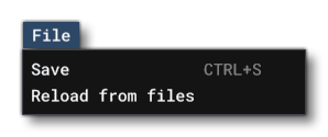
Save
This will save the current graph file being edited. Note that if the file belongs to a preset or an attachment and there are nodes, edges, etc... in the common (or any other) folder, then those will be shown in the editor, but you cannot remove those nodes, and any edits and saves will be done in the current context.
-
Reload From Files
This will reload the navigation graph data from the source files, overwriting any changes that have been made and not saved.
Edit

-
Undo
This will undo the last action performed in the editor. You may useCtrl+Zas a shortcut.
-
Redo
This will redo the last action that was undone in the editor (if an action exists to redo). You may useCtrl+Yas a shortcut.
The Graph Editor Tabs
In the Graph Editor Tab, there will always be a Main Graph tab, and you may also have one or more, optional, Sub Graphs which can be used as part of the Main Graph. Both types of tab are functionally the same: an area where you can use the right-button menu to add nodes, and then connect those nodes with edges to create a full graph.
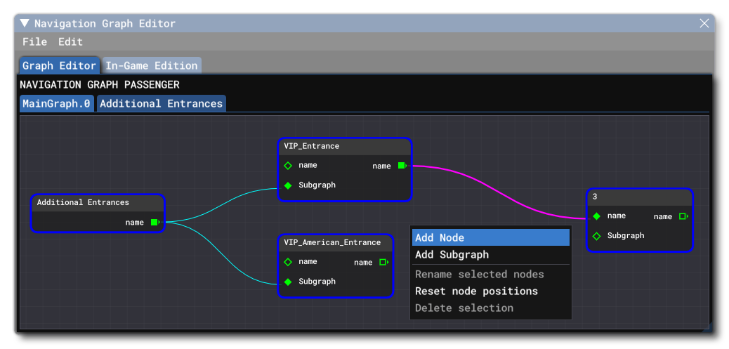
The available context menus that you can access using the Right Mouse Button are as follows:
-
RMB In The Navigation Graph
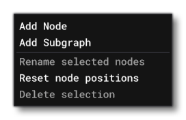
- Add Node: This will add a node to the Main or Sub Graph.
- Add Sub Graph: This will add a Sub Graph node to the Main Graph.
- Rename Selected Nodes: Selecting this option will open a window with name fields for each of the selected nodes. You can then rename them as you require before pressing the
Okbutton to save the change. - Reset Node Positions: This will reset the nodes to the default positions within the graph view.
- Delete Selection: This will delete all the selected items (you can multi-select items by left clicking in the graph window and dragging over one or more nodes and/or edges).
-
RMB On A Node
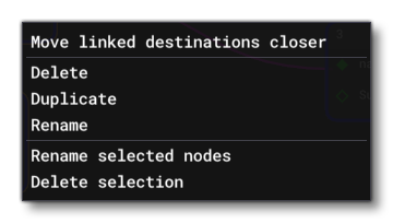
- Move Linked Destinations Closer: Selecting this will move all nodes that this one connects to closer.
- Delete: This will delete the node that has been clicked on.
- Duplicate: This will create a duplicate of the node that has been clicked on.
- Rename: Selecting this option will open a window with a name field for the node. You can then rename it as you require before pressing the
Okbutton to save the change. - Rename Selected Nodes: Selecting this option will open a window with name fields for each of the selected nodes. You can then rename them as you require before pressing the
Okbutton to save the change. - Delete Selection: This will delete the node that has been clicked on as well as any other nodes that have been included in the selection (you can multi-select items by left clicking in the graph window and dragging over one or more nodes and/or edges).
-
RMB On An Edge
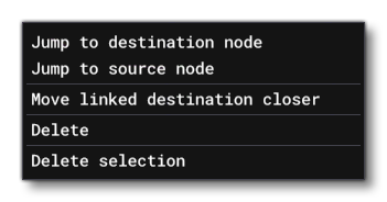
- Jump To Destination Node: Jump the graph view to center on the destination node for the edge.
- Jump To Source Node: Jump the graph view to center on the source node for the edge.
- Move Linked Destination Closer: This option will move all the connected destination nodes closer.
- Delete: This will delete the edge.
- Delete Selection: This will delete the edge that has been clicked on as well as any other edges that have been included in the selection (you can multi-select items by left clicking in the graph window and dragging over one or more nodes and/or edges).
The In-Game Edition Tab
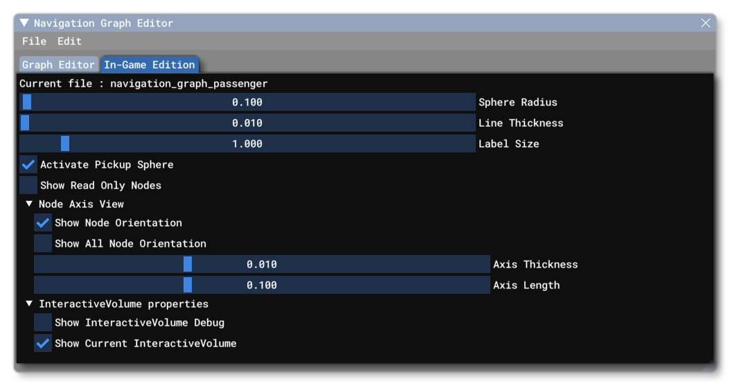 This tab is used to control how the nodes and edges defined in the Navigation Graph will be displayed directly in the simulation, permitting you to debug them and edit them directly using The Edition Gizmo. This tab has the following options:
-
Current File
This shows the name of thenavigation_graph.cfgthat is currently being edited.
-
Sphere Radius
This controls the size of the wire-frame marker sphere used to illustrate the position of graph nodes.
-
Line Thickness
This controls the thickness of the marker lines used to show the edges connecting nodes.
-
Label Size
This controls the display size of the node label (tag).
-
Activate Pickup Sphere
When checked, you can click on the node sphere to activate The Edition Gizmo and edit the position and rotation of the node directly within the simulation.
-
One-Click Placing
When you select this option, the simulation will show a pickup sphere attached to the mouse cursor, and you can click anywhere within the scene to place a navigation graph node. On click, a sub-window will open allowing you to name the node without having to go to other windows:

-
Show Read Only Nodes
When checked, nodes that have been flagged as "Read only" will be shown, even though they cannot be edited.
-
Node Axis View
This section shows the different options related to the node axis visualisation.- Show Node Orientation: When checked, the selected node spheres will also show the orientation of the node.
- Show All Node Orientations: When checked, the all node spheres will also show the orientation of the node.
- Axis Thickness: Lets you set the thickness of the axis indicator lines.
- Axis Length: Lets you set the length of the axis indicator lines.
-
Interactive Volume Properties
This section shows the different options related to the interaction volume visualisation.- Show Interactive Volume Debug: When checked, any volumes defined for the aircraft will be shown as a simple wire-frame cuboid. The cuboid will be purple if the node is not selected, and orange if the node is selected.
- Show Current Interactive Volume: When checked, the current selected node will display a simple, orange, wire-frame cuboid illustrating the defined volume for the node, even if the Show Debug Volume option is unchecked.
The following options will be available only when editing a navigation graph in The Scenery Editor:

-
Set Cur Node To Aircraft Pos
Clicking this button will set the currently selected node position to that of the user aircraft. Note that this requires The Edition Gizmo to have been enabled for the node. This is done from Node section in either the SimObject Editor (for SimObjects), or The Navigation Graph CFG Editor (for Airports).
-
Snap Cur Node To Ground
When this is checked, the current node will be snapped to the ground, and any edition done using the Gizmo will only be on the X/Y axis, with the Z axis being automatically snapped to the ground normal.
-
Snap Cur Node To Ground
- When this is check, the currently selected node will be snapped to the ground. If checked with One Click Placing, then every node created with a click will be snapped to the ground automatically.
-
One Click Placing
- When this is enabled, you simply need to click in the scene for a node to placed at the mouse position.
The Navigation Graph CFG Editor
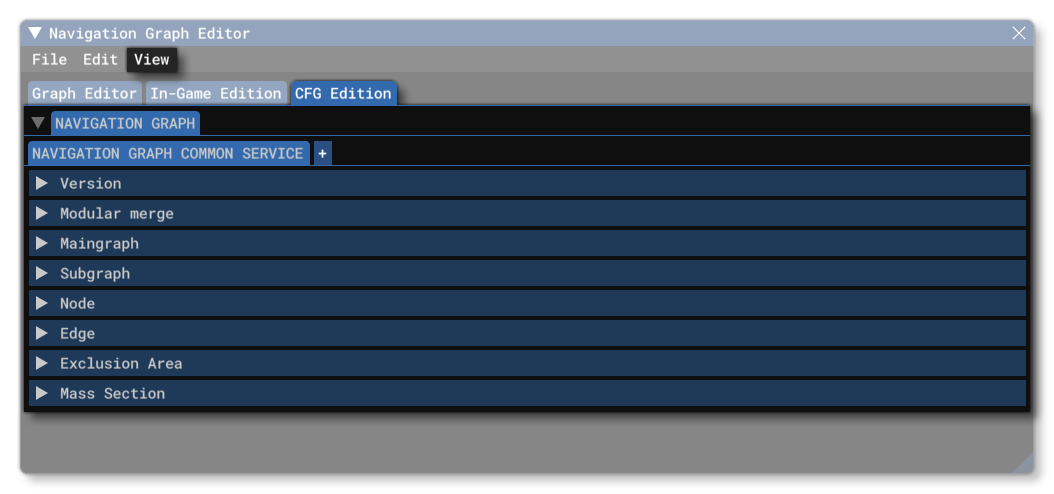
This window will only be shown when working with navigation graphs in The Scenery Editor, specifically when editing Airport packages.
NOTE: When editing BGL airport packages, you can still open the navigation graph editor and add data to it, however this will be ignored when the package is added to the simulation.
Initially the window will be empty, as you will have to add a navigation graph file to be able to edit. You will also have an extra menu item at the top of the window.
View

-
Use Legacy
When this checkbox is checked, the the CFG tabs will show those parameters that are considered part of the legacy simulation. These parameters have generally been deprecated within the current modern world model, and so have no requirement for being set. However, they may still be required for legacy SimObjects or Scenery from previous versions of the simulation that have been ported into the current version, and as such this checkbox can be used to flag the object as one of these. Note that if you have already saved an object previously as a legacy object then this check box will not be automatically checked when it is loaded into the editor, and you will need to manually enable it to see the appropriate parameters in the editor (the parameter data will still have been loaded, even if it's not immediately visible).
-
Show Parameter Names
When this option is checked, the Navigation Graph Editor will show the actual parameter names that will be saved to thenavigation_graph.cfgfile instead of the more explicit common names typically shown.
Navigation Graph Tab
Navigation graph CFG files are added by selecting the Navigation Graph tab, and then clicking on the + button. You will be asked to give the file a name, and then the file will be created and be ready for you to edit it. Files should always follow this naming schema:
navigation_graph_[SimObjName]_<Identifier>.cfg
navigation_graph_[AirportICAO]_<identifier>.cfg
IMPORTANT! You cannot have a file called simply navigation_graph.cfg. This will cause issues, both with the editor and potentially with the simulation itself.
You can create multiple files per airport, and each one will have it's own tab and can be edited independently within the editor and the airport scene. For more information on the contents of this file (and the options available in the Navigation Graph CFG Editor), please see the following pages:
Custom Parameters Tab
The Navigation Graph editor may also have a Custom Parameters tab. This tab is there to show any issues with the file, or to show any parameters that have been added manually. Please see here for more information: