AIRFRAME TEXTURES AND MATERIALS
This section of the art documentation deals with the way that textures should be applied to the Airframe meshes. This page lists some general rules and guidelines that should be adhered to when texturing the aircraft, and then links to pages containing information about specific parts or procedures. Before continuing with this section, we recommend that you revise the following pages:
IMPORTANT: AO/Roughness/Metal (COMP) textures will be compressed into ktx2 format files when packaged by Microsoft Flight Simulator 2024 for distribution. You can alter the default compression levels by editing the FLAGS information in the XML - as explained here: Texture Tool - and you can find additional information on this file format here: KTX2 And KTX2P Files
IMPORTANT! When working with anything that requires modifying the vertex alpha, there may be issues caused by a bug in 3DS Max. This can easily be resolved, however, and the process is explained here: Notes On Vertex Alpha
Unwrapping Efficiency
Efficient use of space is important, you will have texture decals for details, so in most cases you can mirror mapping to save space. Bear in mind that the livery for the plane will be baked to the UVs from the first or second LOD down, so asymmetrical livery designs will need to be taken into account when choosing what UVs to mirror.
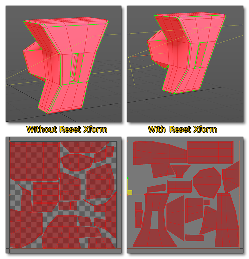
The first thing to do before unwrapping the UVs is to apply a Reset XForm on the object to prevent any unfold problems regarding the proportions. To give an example, we will just show two images of a simple automatic unwrap of the same object - one has a Reset Xform where the other doesn't.

We can see that the unwrapping is different for each of them, but the most important thing is that the shape of the different UVs: without the reset Xform, the unwrapping doesn't bother about things like the scale of the object.
Any normal baking and future LOD mesh reductions should be considered when doing the UV mapping. You should have minimal seams, but a well relaxed mesh in order to gain the best resolution from your textures.
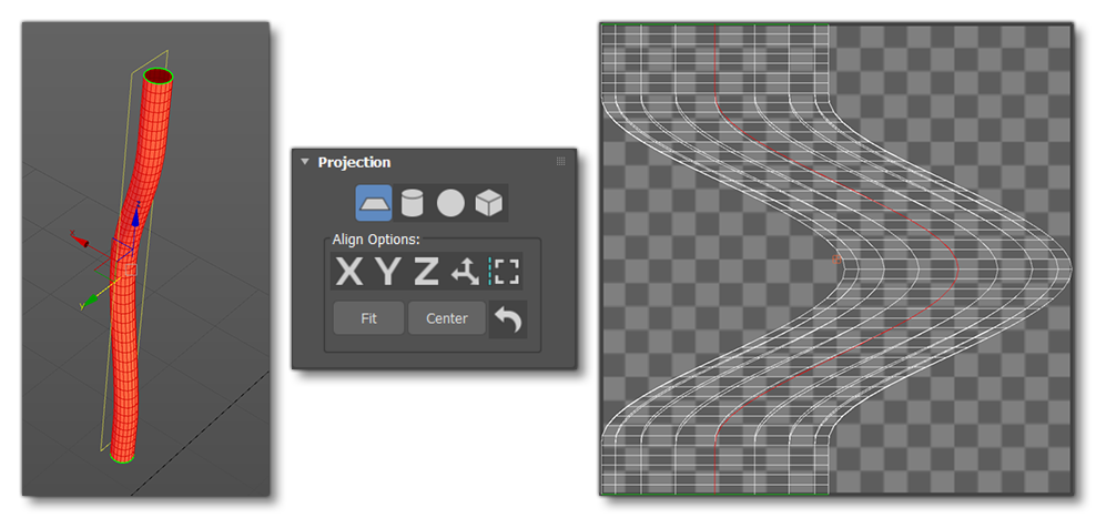
One of the easiest ways to unwrap a cable or a lot of shapes is to apply a planar mapping first, then select an edge loop and separate it:

When that has been done you can use the Relax Tool, or even the Peel Tool (which can sometimes give really good results quickly). The automatic mapping tool is also another solution to use when working with complex shapes. Note that things like cables should be mapped as rectangles along the U or V axis, especially if they have some ribbed normal mapping, as this will give the best resolution.
Finally, here's a list of general recommendations:
- Pay extra attention to the Visual References when mapping your aircraft components, especially the fuselage, as anything that is asymmetrical will need to be mapped accordingly.
- Avoid having seams down the centers of panels as any normal detail will show a seam, and this is especially noticeable on the nose of the plane as it will be right in front of the pilot camera.
- Efficient use of space is important: you will have texture decals for details, so in most cases you can mirror mapping to save space.
- When you unwrap the UVs, please keep in mind that other users can create their own liveries. That's why you cannot overlap parts that could receive a livery.
- Bear in mind that the livery for the plane will be baked to the UVs from the first or second LOD down, so asymmetrical livery designs will need to be considered when choosing what UVs to mirror.
Texel Density Limitations
To map the entire length of the plane with the correct texel density for close up camera shots, there would be far more textures than the engine can handle. In this case, the entire length of a small-to-medium sized aircraft should be mapped on a 2k sheet, with decals providing the correct resolution for the details and livery. However, for any larger planes you should break the mapping up - the 747, for example, has several divisions so that a full airplane length has approximately 5k pixels.
NOTE: When the airframe objects are unwrapped you can use the automatic Arrange Element tool in the UV Editor to arrange them with the same texel density, since 3DS Max will resize all the elements for you. Note that you may be required to do a Reset Xform before using the tool, and some manual arrangement will still be required after this step to fully optimize the UV set.
Texture Budget
A typical texture budgets for an aircraft (including cockpit) is between 150MB for small aircraft and 600MB for large aircraft. Since the *.ktx2 format is a GPU-ready format, the size of the textures on disk is more or less what the game will be using in texture memory. Thus, the texture memory used by your add-ons can easily be determined by looking at the package output's texture folders.
To further help you understand the texture budget available to your aircraft, we have prepared the following table of recommendations for texture sizes based on parts breakdown:
| 256 x 256 and below | 512 x 512 | 1024 x 1024 | 2048 x 2048 | 4096 x 4096 | KEY | |
|---|---|---|---|---|---|---|
| Fuselage | ■ - Good general size ■ - DNot ideal, but depends on object ■ - Shouldn't be this size (except for flat albedo/normal used for optimisation) ■ - Should never be this size |
|||||
| Wings | ||||||
| Landing Gear | ||||||
| Wheels | ||||||
| Details | ||||||
| Rivets / Screws | ||||||
| Decals |
UV Precision
It is important to be aware that the UV data for packaged gLTF files is stored as 2-byte floating point numbers, instead of regular floats, to save on memory usage. This can cause precision issues, particularly with tiling where the UVs could be quite high. For more information on this, please see the UV Precision section on the General Principles page.
Vertices Vs. Texture Space
The Microsoft Flight Simulator 2024 engine prefers mesh over texture resolution, therefore more geometry can be spent on defining the fine detail that would otherwise be defined with normal maps. However, you should still use normal maps for rivets, micro-bump surface detail, and organic surfaces.
You can also use normal maps for very small detailed areas that would otherwise use up a lot of triangles, such as areas that involve a lot of cabling, chassis pressings, screws etc...

Texture Packing
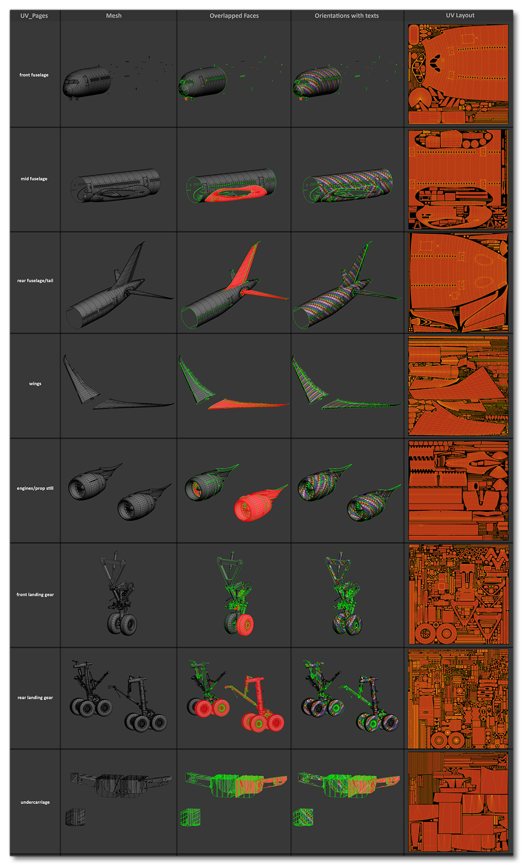
All UV sheets should be packed as efficiently as possible leaving minimal wasted texture space, and you should also try to ensure that elements with close UVs are packed close to each other as well. The following table shows some examples:

Texture Padding
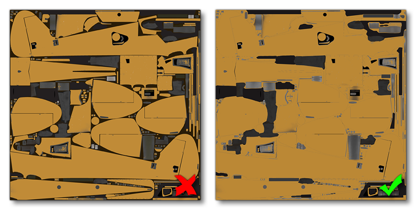
When it comes to preparing the actual textures, especially the Albedo, it is strongly recommended that you have infinite padding dilation. This will dilate the borders of the UV islands to fill empty areas with similar pixels, creating "padding" around the main textures. This is incredibly important when it comes to generating mip-maps, as having poor padding will lead to issues in the simulation. The image below shows what not to do and how a properly padded texture should look:
