PREFLIGHT
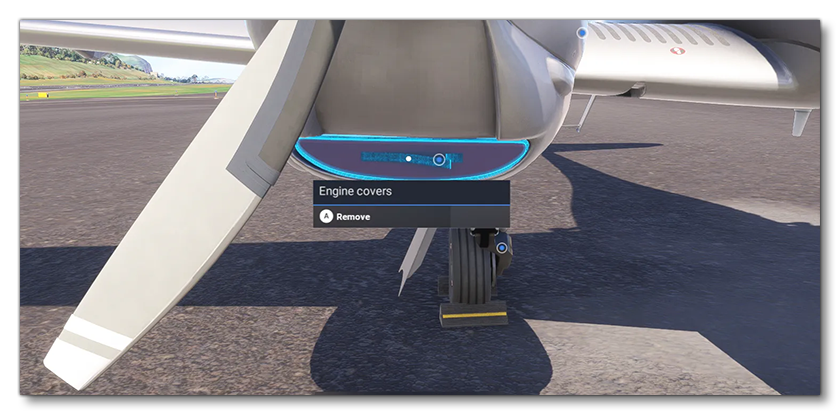
Preflight is the first phase of a flight when the pilot starts "cold and dark" from a parking spot / ramp. The pilot character will spawn at a set spawn-point close to the currently selected aircraft, and it will be possible for them walk around and check the condition of different parts (indicated with a blue pin in the UI). During these preflight checks it will be possible to remove engine covers, pitot / static port protections, gear pins, etc... Afterwards, the user can have their pilot enter the aircraft by interacting with a meaningful part (door, canopy, etc…). The image below shows one of these preflight interactions where the user hovers over an engine cover and is shown a tooltip message that allows them to remove it:
IMPORTANT! Before continuing you should ensure that you have set up the Spawn Pilot (Transversal) navigation graph.
When it comes to the different preflight interactions that the pilot can have with the aircraft, they fall into the following four categories:
- Removing elements (covers, chocks, etc…).
- Checking parts (either by looking at them or moving them).
- Opening traps / doors.
- Entering / exiting the aircraft.
The rest of this page will explain how to set up these interactions. Note that this page assumes you have already set up the aircraft model correctly, specifically the following parts:
Note For The Model Behavior XML
In many places on this page there will be examples of XML to be used in the Model Behavior file for the aircraft or aircraft part (if the aircraft is modular). Most of this XML will use specific Model Behavior Templates to perform the different tasks and interactions. However to be able to use these templates you will need to have set up the main XML files to include them as part of the package:
<?xml version="1.0" encoding="utf-8"?>
<ModelInfo>
    <LODS>
        <!-- LODs Here -->
    </LODS>
    <CompileBehaviors version="2">
        <Include ModelBehaviorFile="Asobo_EX1\Index.xml" />
        <Include ModelBehaviorFile="Asobo_EX1\DefaultConfig.xml" />
        <!-- choose the appropriate template group for interiors / exteriors -->
        <Include ModelBehaviorFile="ASOBO_EX1\ExteriorDefs.xml"/>
        <Include ModelBehaviorFile="ASOBO_EX1\InteriorDefs.xml"/>
        ...
        <!-- Components Here -->
        ...
    </CompileBehaviors>
</ModelInfo>
With this basic structure you will have available all the templates that are included as part of the SDK and that are used on this page. You can find the full list of included templates here:
NOTE: All the core behaviour files for Microsoft Flight Simulator 2024 are in the Asobo_EX1 folder. The core files for Microsoft Flight Simulator 2020 are in the Asobo folder. You should not mix and match templates from both folders. They may work together, but future updates may break this and in general all aircraft for MSFS 2024 should use the Asobo_EX1 templates.
Removing Simple Elements
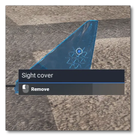
Simple elements are elements which do not prevent the aircraft from flying if they are not removed, and they have no consequence for performances, wear, instrument functionality, etc... Essentially they are cosmetic elements that are including the preflight checks for immersion and realism. For example, the covers on the wing tips of the E330 LT can be removed using a simple interaction but will have no effect on the aircraft if they are not removed:
XML Setup - Simple Interaction
To create these types of simple interactions, you will need to set up your interaction in the corresponding XML file for the part. The example shown below comes from the Wing_Left.xml file for the E330 LT:
<Component ID="INTERACTIONS">
    <!-- interact with -->
    <UseTemplate Name="ASOBO_CT_Toggle_Interaction_Template">
        <IN_BASE_NAME>COVER_SIGHT_LEFT</IN_BASE_NAME>
        <IE_NAME>COVER_SIGHT_LEFT_HIDER</IE_NAME>
        <VAR_NAME>XMLVAR_COVER_WING_LEFT</VAR_NAME>
        <TOOLTIP_ID>SIGHT_COVER</TOOLTIP_ID>
        <NO_TOOLTIP_VALUE/>
        <IE_TOOLTIP_DESCRIPTION_ID>@TT_Package.ACTION.REMOVE</IE_TOOLTIP_DESCRIPTION_ID>
    </UseTemplate>
    <UseTemplate Name="ASOBO_GT_Component_Visibility_Template">
        <NODE_ID>COVER_SIGHT_LEFT</NODE_ID>
        <COMPONENT_ID>COVER_SIGHT_LEFT_HIDER</COMPONENT_ID>
        <VISIBILITY_CODE>(L:1:XMLVAR_COVER_WING_LEFT, Bool) !</VISIBILITY_CODE>
    </UseTemplate>
</Component>
In this example, the first section is using the ASOBO_CT_Toggle_Interaction_Template, and linking it with the XML variable XMLVAR_COVER_WING_LEFT so that when the user clicks the COVER_SIGHT_LEFT element it will toggle the variable between the values of 0 and 1. The second section is simply using the ASOBO_GT_Component_Visibility_Template to check the value of this XML variable and then set the visibility of the cover object accordingly. You will need to create interactions like this for each one of the simple covers that you want the user to be able to interact with.
NOTE: The node name given in all examples is the name of the object node in the aircraft model, with the LOD prefix stripped. For example, above we have COVER_SIGHT_LEFT which corresponds to the x0_COVER_SIGHT_LEFT mesh.
FLT Setup - Simple Interaction
The XML variable used in the XML shown in the section above needs to be created before it can be used, and this is done in the FLT Files, specifically the apron.flt and the hanger.flt, which are the files that will be used to setup the aircraft when it spawns on a parking spot or in a hanger. These XML variables are added into the [LocalVars_EX1.N] section of the file and should be set to 0 (o is covered, 1 is uncovered):
[LocalVars_EX1.0]
XMLVAR_COVER_WING_LEFT=0
XMLVAR_COVER_WING_RIGHT=0
You will need to set up variables like this for each of the simple interactions that you wish the user to be able to perform on the aircraft.
Removing Necessary Elements (Covers, Chocks and Pins)
Necessary elements are those which will have some kind of consequence if they are not removed as part of the preflight checkup. For example:
- Leaving engine covers will prevent engines from starting.
- Leaving pitot and static covers will prevent some instruments from working correctly (airspeed, altimeter, etc…).
- Leaving gear pins will prevent the landing gear from retracting.
- Leaving chocks will prevent the aircraft from moving.
- Leaving propeller and rotor covers will prevent the propeller or rotor from rotating.

XML Setup - Necessary Interactions
For these kinds of necessary interactions you should be using the ASOBO_ET_COMMON_Cover_Interaction_And_Visibility_Template. This template combines the interaction and visibility toggle, and also includes a specific tag to specify what component the element refers to so that it can be factored into the simulation and generate appropriate consequences if left. The XML snippet shown below is an example for an engine cover interaction:
<Component ID="COVER_ENGINE_2">
    <UseTemplate Name="ASOBO_ET_COMMON_Cover_Interaction_And_Visibility_Template">
        <NO_TOOLTIP_VALUE/>
        <TOOLTIP_ID>ENGINE_COVERS</TOOLTIP_ID>
        <IE_TOOLTIP_DESCRIPTION_ID>@TT_Package.ACTION.REMOVE</IE_TOOLTIP_DESCRIPTION_ID>
        <IE_NAME>COVER_ENGINE</IE_NAME>
        <IN_BASE_NAME>COVER_INTAKES</IN_BASE_NAME>
        <NODE_ID>COVER_INTAKES</NODE_ID>
        <COVER_FLAG>@COVER_ENGINE</COVER_FLAG>
    </UseTemplate>
</Component>
The tag <COVER_FLAG> is where you tell the simulation what system to link the element to so that the correct response to it's non removal can be calculated. The possible element IDs are as follows:
@COVER_ENGINE- Used for engine covers@COVER_CHOCKS- Used to remove the chocks from the wheels@COVER_PITOT- Used to remove the pitot cover@COVER_STATIC_PORT- Used to remove any static port covers@COVER_PITOT_AND_STATIC- Used to remove the cover from dual-purpose probes@COVER_ROTOR- Used to remove rotor blade covers@COVER_LANDING_GEAR- Used to remove the landing gear pins@COVER_PROPELLER- Used to remove propeller covers
IMPORTANT! When removing a tagged element, all the other elements with the same tag will also be removed.
FLT Setup - Necessary Interactions
As with simple interactions, the necessary interactions will also need a small amount of setup to be done in the appropriate FLT files (the apron.flt and the hanger.flt). In these files you will need to specify what covers are being used in the [Covers] section of the file, for example:
[Covers]
Chock=On
Engine=On
Pitot=On
Static_Port=On
It is important to note that anything not mentioned in this section will be considered as having the covers removed.
Alternative XML For Small And Skinned Elements
In some cases, the interactive element can be quite small - eg: a gear pin - or it can belong to a skinned mesh in the model - eg: rotor blade covers. As explained in the art documentation (see here: Additional Collision Meshes), for these cases you will have made an additional collision mesh specifically to facilitate the preflight interactions. In these case - since the collision mesh is separated from the modeled pin asset - you can’t use the all-in-one solution that the ASOBO_ET_COMMON_Cover_Interaction_And_Visibility_Template gives you. Instead you will have to use the following two templates:
ASOBO_ET_COMMON_Toggle_Cover_Interaction_Template- This is used to set the interactionASOBO_ET_COMMON_Cover_Visibility_Template- This is used to toggle the asset and collision visibility
To deal with this, when setting up the interaction in the XML, you will also have to specify what node you want to highlight when the collision box is hovered. This is done using the tag <MOUSERECT_HIGHLIGHT_NODE_ID>, as shown in the example below:
<Component ID="COVER_FRONT_LANDING_GEAR_1">
    <UseTemplate Name="ASOBO_ET_COMMON_Cover_Visibility_Template">
        <NODE_ID>COVER_FRONT_LANDINGGEAR_COLLISION</NODE_ID>
        <COVER_FLAG>@Cover_Landing_Gear</COVER_FLAG>
    </UseTemplate>
    <UseTemplate Name="ASOBO_ET_COMMON_Cover_Visibility_Template">
        <NODE_ID>COVER_FRONT_LANDINGGEAR</NODE_ID>
        <COVER_FLAG>@Cover_Landing_Gear</COVER_FLAG>
    </UseTemplate>
    <Component ID="COVER_FRONT_LANDING_GEAR_2">
        <UseTemplate Name="ASOBO_ET_COMMON_Toggle_Cover_Interaction_Template">
            <TOOLTIP_ID>GEAR_PIN</TOOLTIP_ID>
            <NO_TOOLTIP_VALUE/>
            <IE_TOOLTIP_DESCRIPTION_ID>@TT_Package.ACTION.REMOVE</IE_TOOLTIP_DESCRIPTION_ID>
            <IE_NAME>PIN_FRONT_LANDINGGEAR</IE_NAME>
            <IN_BASE_NAME>COVER_FRONT_LANDINGGEAR_COLLISION</IN_BASE_NAME>
            <MOUSERECT_HIGHLIGHT_NODE_ID>COVER_FRONT_LANDINGGEAR</MOUSERECT_HIGHLIGHT_NODE_ID>
            <COVER_FLAG>@Cover_Landing_Gear</COVER_FLAG>
        </UseTemplate>
    </Component>
</Component>
Checking Aircraft Parts
Apart from removing covers, chocks, and pins, an important part of the preflight checks is to perform a visual and physical inspection of the various different aircraft parts which may be subject to wear and tear.
Visual Checks
Visual checks are those that simply involve the user to mouse over an item and then click to signify a "visual" check of the part selected. This kind of interaction is very simple to set up using the ASOBO_CT_Observe_Interaction_Template. For example, the XML below shows the setup for a simple visual check of the left flaps:
<Component ID="INTERACTION">
    <UseTemplate Name="ASOBO_CT_Observe_Interaction_Template">
        <TOOLTIP_ID>LEFT_FLAP</TOOLTIP_ID>
        <IE_TOOLTIP_DESCRIPTION_ID>@TT_Package.ACTION.CHECK</IE_TOOLTIP_DESCRIPTION_ID>
        <IN_BASE_NAME>LEFTFLAP2</IN_BASE_NAME>
        <IE_NAME>LEFT_FLAP</IE_NAME>
        <SaveParameters ID="WearAndTearElements">
            <FLAPS_LEFT/>
        </SaveParameters>
    </UseTemplate>
</Component>
The important thing to note here is that the parts being visually checked should be part of the wear and tear system, since the value used to define their current state is saved and as such you can only specify specific items as a sub-element. You can find a full list of the available sub-element tags here: Wear And Tear XML Tags
It is also possible to target some specific parts by supplying a name for the tag. For example the <BRAKE />, <TIRE />, <TIRE_PRESSURE />, and <LANDING_GEAR /> tags should specify which landing gear is being checked by giving them the name of the landing gear as defined in the [CONTACT_POINTS] section of the flight_model.cfg file. For example, in the DA62, you have the following named contact point:

Using the name in the XML requires you to use the format 'ITEM_NAME'_n in the file, for example, here is the DA62 interaction XML for the left wheel, using the name of the gear contact point as specified in the flight_model.cfg file:
<Component ID="INTERACTIONS">
    <!-- tire -->
    <UseTemplate Name="ASOBO_CT_Observe_Interaction_Template">
        <TOOLTIP_ID>REAR_WHEEL</TOOLTIP_ID>
        <IE_TOOLTIP_DESCRIPTION_ID>@TT_Package.ACTION.CHECK</IE_TOOLTIP_DESCRIPTION_ID>
        <IN_BASE_NAME>PF_COLLISION_TIRE_CENTER</IN_BASE_NAME>
        <MOUSERECT_HIGHLIGHT_NODE_ID>TIRE_STILL_CENTER</MOUSERECT_HIGHLIGHT_NODE_ID>
        <IE_NAME>REAR_WHEEL</IE_NAME>
        <SaveParameters ID="WearAndTearElements">
            <TIRE>'WHEEL_CENTRAL'_n</TIRE>
            <TIRE_PRESSURE>'WHEEL_CENTRAL'_n</TIRE_PRESSURE>
        </SaveParameters>
    </UseTemplate>
</Component>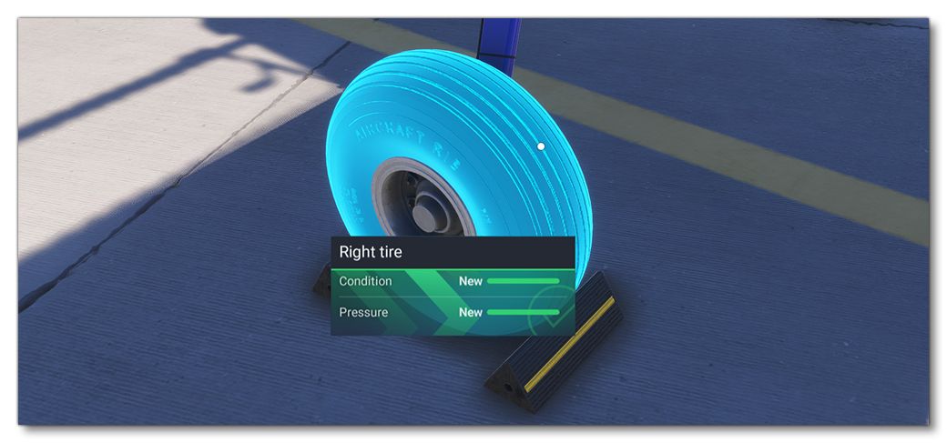
Physical Checks
There are three elements on the aircraft that have templates permitting physical checks. These are checks that permit the user to select the part and then manipulate it to ensure that it's working correctly. These are set up in a similar way to the visual checks, but require the use of one of the following templates (depending on the part being checked):
ASOBO_CT_Aileron_Interaction_TemplateASOBO_CT_Elevator_Interaction_TemplateASOBO_CT_Rudder_Interaction_Template
There are specific Wear And Tear XML Tags to be used with these templates as well. Below is an example of the XML setup for a physical check of the left aileron:
<Component ID="INTERACTIONS">
    <UseTemplate Name="ASOBO_CT_Aileron_Interaction_Template">
        <TOOLTIP_ID>LEFT_AILERON</TOOLTIP_ID>
        <IE_TOOLTIP_DESCRIPTION_ID>@TT_Package.ACTION.CHECK</IE_TOOLTIP_DESCRIPTION_ID>
        <IN_BASE_NAME>LEFTAILERON1</IN_BASE_NAME>
        <IE_NAME>LEFT_AILERON</IE_NAME>
        <CALLBACK_DRAG_ANIM_NAME>L_AILERON_PERCENT_KEY</CALLBACK_DRAG_ANIM_NAME>
        <CALLBACK_DRAG_SCALAR_BOOST>1.5</CALLBACK_DRAG_SCALAR_BOOST>
        <INVERT_DRAG_SCALAR>True</INVERT_DRAG_SCALAR>
        <SaveParameters ID="WearAndTearElements">
            <AILERONS_LEFT/>
        </SaveParameters>
    </UseTemplate>
</Component>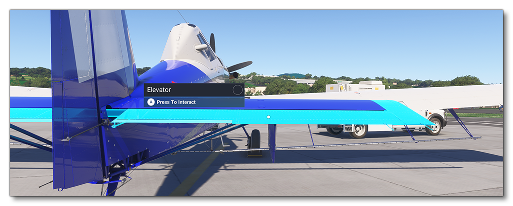
Multi-Object Interaction And Highlighting
Sometimes you will want to shown an interaction with an element made up of multiple parts, for example a landing gear strut comprised of the strut itself, hydraulics connections, and a brake disk. The goal here is to ensure that if the user hovers over any of the sub-parts, all the other related sub-parts will also be highlighted. Setting this up is very similar to the other interactions, using one of the templates, but repeated and targeting the different parts. Here's the XML for the DA62 combining 3 different sub-parts under a single interaction:
<Component ID="Nose_gear_observation">
    <Parameters Type="Override">
        <UPDATE_VAR_SCOPE>L:1</UPDATE_VAR_SCOPE>
        <UPDATE_VAR_NAME>XMLVAR_Observing_Nose_Gear</UPDATE_VAR_NAME>
    </Parameters>
    <UseTemplate Name="ASOBO_CT_Observe_Interaction_Template">
        <TOOLTIP_ID>NOSE_STRUT</TOOLTIP_ID>
        <IE_TOOLTIP_DESCRIPTION_ID>@TT_Package.ACTION.CHECK</IE_TOOLTIP_DESCRIPTION_ID>
        <IN_BASE_NAME>PF_COLLISION_GEAR_HYDRAULIC_B_CENTRAL_01</IN_BASE_NAME>
        <NODE_ID>GEAR_HYDRAULIC_B_CENTRAL_01</NODE_ID>
        <PART_ID>FRONT_GEAR</PART_ID>
        <MOUSERECT_HIGHLIGHT_PART_ID>FRONT_GEAR</MOUSERECT_HIGHLIGHT_PART_ID >
        <IE_NAME>FRONT_LEG_1</IE_NAME>
        <SaveParameters ID="WearAndTearElements">
            <LANDING_GEAR>'WHEEL_CENTRAL'_n</LANDING_GEAR>
        </SaveParameters>
    </UseTemplate>
    <UseTemplate Name="ASOBO_CT_Observe_Interaction_Template">
        <TOOLTIP_ID>NOSE_STRUT</TOOLTIP_ID>
        <IE_TOOLTIP_DESCRIPTION_ID>@TT_Package.ACTION.CHECK</IE_TOOLTIP_DESCRIPTION_ID>
        <IN_BASE_NAME>GEAR_HYDRAULIC_A_CENTRAL_01</IN_BASE_NAME>
        <IE_NAME>FRONT_LEG_2</IE_NAME>
        <PART_ID>FRONT_GEAR</PART_ID>
        <MOUSERECT_HIGHLIGHT_PART_ID>FRONT_GEAR</MOUSERECT_HIGHLIGHT_PART_ID >
        <SaveParameters ID="WearAndTearElements">
            <LANDING_GEAR>'WHEEL_CENTRAL'_n</LANDING_GEAR>
        </SaveParameters>
        <NO_PROGRESS_UPDATE>True</NO_PROGRESS_UPDATE>
    </UseTemplate>
    <UseTemplate Name="ASOBO_CT_Observe_Interaction_Template">
        <TOOLTIP_ID>NOSE_STRUT</TOOLTIP_ID>
        <IE_TOOLTIP_DESCRIPTION_ID>@TT_Package.ACTION.CHECK</IE_TOOLTIP_DESCRIPTION_ID>
        <IN_BASE_NAME>GEAR_STEERING_CENTRAL</IN_BASE_NAME>
        <IE_NAME>FRONT_LEG_3</IE_NAME>
        <PART_ID>FRONT_GEAR</PART_ID>
        <MOUSERECT_HIGHLIGHT_PART_ID>FRONT_GEAR</MOUSERECT_HIGHLIGHT_PART_ID >
        <SaveParameters ID="WearAndTearElements">
            <LANDING_GEAR>'WHEEL_CENTRAL'_n</LANDING_GEAR>
        </SaveParameters>
        <NO_PROGRESS_UPDATE>True</NO_PROGRESS_UPDATE>
    </UseTemplate>
</Component>
In this case, the strut to check is made of 3 sub-parts and we want them all to be interactive and highlight when any of them are hovered over. Also note that despite the component being made of 3 sub-parts, there is only one wear and tear element that it corresponds to, the front landing gear.
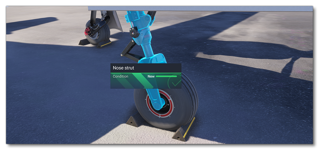
Here you can see the entire landing gear highlighted and involved in a single interaction, and all this is done using a single variable. In this case it's the parameter XMLVAR_Observing_Nose_Gear, which has been added to the [LocalVars_EX1.N] section of the FLT File. Note that you can choose the variable name you want for these things, as long as there is no duplicate parameter defined anywhere else for the aircraft. The rest of the XML is basically the same code repeated for all three parts that we want to include in the interaction, differentiated using the <NODE_ID> to specify the part of the model mesh to include, and linked to each other by the use of the same <PART_ID> (which is FRONT_GEAR for all of them).
One very important thing to note about this code is the use of the <NO_PROGRESS_UPDATE> tag in two of the three element definitions. Only one of the sub-parts should be designated for updating the associated wear and tear variable, and all others should have:
<NO_PROGRESS_UPDATE>True</NO_PROGRESS_UPDATE>If this isn't included in all sub-elements except one, then the XML variable will update the wear and tear status of the landing gear each time the user hovers a different sub-part.
Opening Traps And Cargo Doors
Most aircraft will have some form of cargo door, and there will be "traps" that have door-like covers for fuel and oil. These should be able to be opened and closed as well, whether they are used or not, as this adds to the realism of the aircraft.
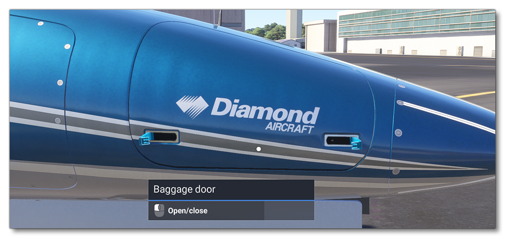
In the majority of cases, you will set the full door object as interactive, but only want to highlight the handles (unless they are barely visible, in which case it is better to highlight the entire door), and so you will need to give 3 different pieces of information from the model: the main door node, the handle node, and the animation group name. These will all be given to the ASOBO_CT_Toggle_Interaction_Template template, which will look something like this:
<Component ID="CARGO_INTERACTIONS">
    <UseTemplate Name="ASOBO_CT_Toggle_Interaction_Template">
        <IN_BASE_NAME>SKEL_LUGGAGE_DOOR_LEFT</IN_BASE_NAME>
        <IE_NAME>CARGO_LEFT</IE_NAME>
        <ANIM_NAME>LUGGAGE_OPEN_LEFT</ANIM_NAME>
        <ANIM_LAG>100</ANIM_LAG>
        <MOUSERECT_HIGHLIGHT_PART_ID>CARGO_LEFT_LOCK</MOUSERECT_HIGHLIGHT_PART_ID>
        <TOOLTIP_ID>COMMON_BAGGAGE_DOOR</TOOLTIP_ID>
        <IE_TOOLTIP_DESCRIPTION_ID>COCKPIT.TOOLTIPSV3.ACTION.OPEN_CLOSE</IE_TOOLTIP_DESCRIPTION_ID>
        <NO_TOOLTIP_VALUE/>
    </UseTemplate>
    <Component ID="INTERIOR_LUGGAGEDOOR_LEFT_HANDLE_1_PARTID" node="INTERIOR_LUGGAGEDOOR_LEFT_HANDLE_1">
        <UseTemplate Name="ASOBO_PartId_Template">
            <PART_ID>CARGO_LEFT_LOCK</PART_ID>
        </UseTemplate>
    </Component>
    <Component ID="INTERIOR_LUGGAGEDOOR_LEFT_HANDLE_2_PARTID" node="INTERIOR_LUGGAGEDOOR_LEFT_HANDLE_2">
        <UseTemplate Name="ASOBO_PartId_Template">
            <PART_ID>CARGO_LEFT_LOCK</PART_ID>
        </UseTemplate>
    </Component>
</Component>
Here we've defined the door interaction along with two individual "handle" parts, which share a part ID. This ID is used in the interaction template as the <MOUSERECT_HIGHLIGHT_PART_ID>, meaning that when the door object is moused over, both the door handles will be highlighted.
Entering / Exiting The Aircraft
During the preflight checks it should be possible for the user to enter and exit the aircraft at will. The general flow for this kind of action is as follows:
- The user clicks on an interactive object (the door) to enter or exit the aircraft.
- The corresponding local variable - either
EXIT_AIRCRAFTorENTER_AIRCRAFT- is set to 1 (see the Enter / Exit XML examples below). - The InteractionFile associated with the pilot navigation graph detects this interaction and sets the interactive point goal position to 100%.
- The internal interactive point system then moves the point value incrementally towards 100% until it matches match the goal position that has been set.
- The animation, which is set up in the model behavior to read the value of enter/exit local variables, also runs based on the interaction point value so the door opens.
- Once the once the interaction point position value is set to 100%, the InteractionFile then triggers the pilot to enter/exit the aircraft, and forces both the interactive point local variables back to 0 to close the door instantly.
Setting up the InteractionFile is discussed in detail on the page linked below, and as such this page will only discuss the setup of the model behaviour XML to detect the initial user interaction, but you will need to set up both if you want to have the player open the door and enter/exit the aircraft.
Enter / Exit XML
Setting up the animations for doors and hatches is explained on the airframe modeling page, so here we'll concentrate on the actual interaction code that will perform set the animation running when the user interacts with the door. As with all other interactions, for this we'll use a model behavior template, specifically ASOBO_CT_Simple_Interaction_Template.
To enter the aircraft you would have something like this in the exterior XML file:
<Component ID="Doors">
<UseTemplate Name="ASOBO_CT_Simple_Interaction_Template">
<TOOLTIP_ID>DOOR</TOOLTIP_ID>
<IE_TOOLTIP_DESCRIPTION_ID>@TT_Package.ACTION.ENTER</IE_TOOLTIP_DESCRIPTION_ID>
<IN_BASE_NAME>SKEL_DOOR_OPEN_1</IN_BASE_NAME>
<IE_NAME>DOOR</IE_NAME>
<ON_EVENT>(L:1:ENTER_AIRCRAFT, Bool) ! (>L:1:ENTER_AIRCRAFT, Bool)</ON_EVENT>
<MOUSERECT_HIGHLIGHT_NODE_ID>DOOR_HANDLE_FRONT_LEFT</MOUSERECT_HIGHLIGHT_NODE_ID>
<NO_TOOLTIP_VALUE/>
</UseTemplate>
</Component>To exit the aircraft you would have something like this in the interior XML file:
<Component ID="Doors">
<UseTemplate Name="ASOBO_CT_Simple_Interaction_Template">
<IN_BASE_NAME>DOORS_FRONT_LEFT_LOCK</IN_BASE_NAME>
<ANIM_NAME>DOOR_OPEN_1</ANIM_NAME>
<IE_ID_SOURCE>DOOR</IE_ID_SOURCE>
<IE_NAME>LOCK</IE_NAME>
<IE_NAME_UID>LEFT</IE_NAME_UID>
<TOOLTIPS_TITLE_PACKAGE>@TT_Package_Project</TOOLTIPS_TITLE_PACKAGE>
<TOOLTIP_ID_WITH_NO_ID>True</TOOLTIP_ID_WITH_NO_ID>
<POINT_ID>1</POINT_ID>
<SOUND_EVENT_TYPE_ID>2</SOUND_EVENT_TYPE_ID>
<IE_TOOLTIP_DESCRIPTION_ID>@TT_Package.ACTION.EXIT</IE_TOOLTIP_DESCRIPTION_ID>
<ON_EVENT>(L:1:EXIT_AIRCRAFT, Bool) ! (>L:1:EXIT_AIRCRAFT, Bool)</ON_EVENT>
<NO_TOOLTIP_VALUE/>
</UseTemplate>
</Component>In both cases the important tag is the <ON_EVENT> tag, which is what controls the entry/exit of the user using the local variables ENTER_AIRCRAFT and EXIT_AIRCRAFT. Note that these do not need to be initialised anywhere else as they will be initialised to 0 the first time they are called, and also note that these variables will be used to trigger the interaction between the user pilot avatar and the doors themselves (as explained here: Pilot Interactions).
The Preflight Navigation Graph
The final part of setting up the preflight interactions is the creation of the preflight navigation_graph.cfg file. This file must be called navigation_graph_preflight.cfg and you may have multiple versions of this file depending on how the aircraft is set up:
- If you have no aircraft variation, you can create only one
navigation_graph_preflight.cfgand put it in the common folder. - If your aircraft has variations, for example a version with wheels and a version with floats, then you can create a "base"
navigation_graph_preflight.cfgfor all the common elements (like flaps, ailerons, elevator, etc…) in the common folder, then add anothernavigation_graph_preflight.cfgcontaining only the nodes which are specific to the variation in the variation folder (like in the wheels variation preset you'd have nodes for brakes, tires, etc..., and in the floats preset you'd have nodes for the water rudder, floats, etc...)
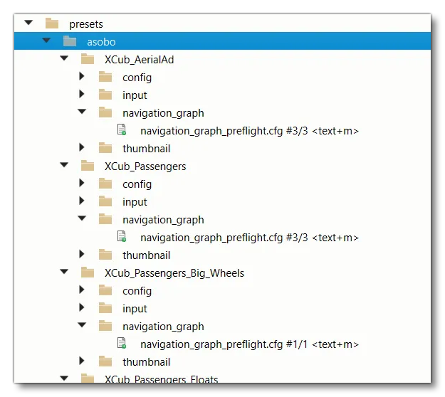
If you create several navigation graphs in various folders, you will need to allow them to be merged when the aircraft is loaded (this merge process is explained here: Modular SimObject Merging), which means each variation will need it's own navigation_graph folder to hold the file, as illustrated in the image below:
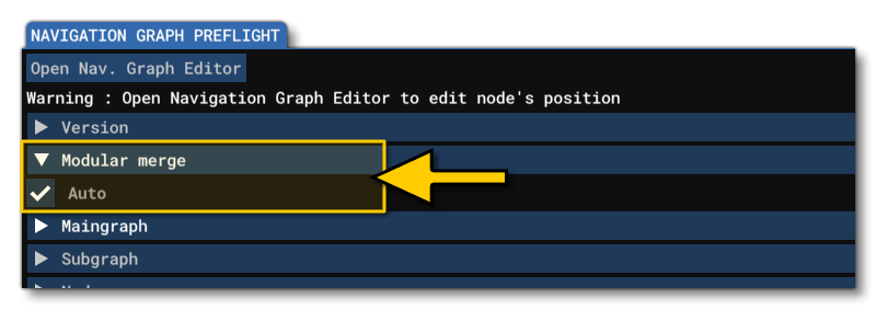
When setting up the aircraft in this way, you will need to ensure that each file - except the one found in the common folder - has been flagged for auto-merging, eg:
Pins and Volumes
Before getting into the setup it's worth understanding the two main concepts behind having the preflight navigation graph, since these are essential to creating correct interactions. These are as follows:
-
Pins
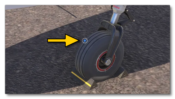
Pins are a visual indicator that a preflight check of some kind can be performed on a specific element related to the pin position, and will be placed at the position of the navigation graph node for the element. The image below shows an example of a pin signalling that an interaction is available for the wheel:
-
Volumes
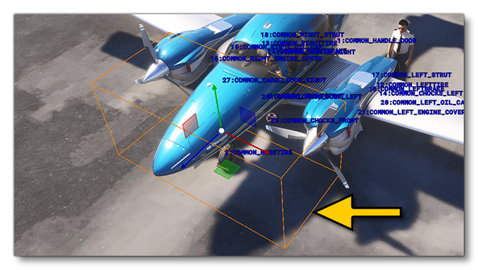
Volumes are invisible areas that are placed around a navigation graph node to define the area within which all interactions with the node will be detected. The user will only be able interact with the part while they are considered inside the volume, and - in some cases - leaving the volume may also trigger an effect like automatically closing a cargo door, or a fuel trap hatch. The image below shows the interactive volume for the same wheel that is shown above:
Node Creation
Nodes are added to the navigation graph from The Navigation Graph Editor and then can be positioned in the world using The Edition Gizmo. Each node that you add will be placed at the Datum Reference Point for the aircraft, and can then be positioned on the required element. In general you will want to take a moment and simply create each of the required nodes and position them around the aircraft where you want the interactive pins to be shown for the part to be inspected.
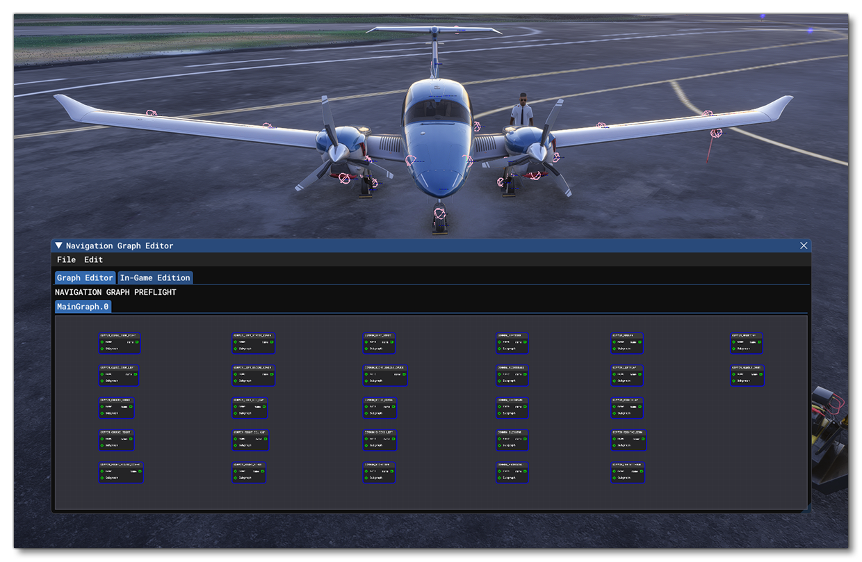
Having done that there are some other things that will need to be done for the nodes, such as giving each of them a tag to identify them, which must be unique for each node. By default all pins associated with nodes will be blue, however the pin associated with the entry/exit door for the pilot should be yellow, which means that this node - and only this node - must be tagged "DOOR". You will also need to define the interactiveVolume area for the node (as explained above).
NOTE: If you are not using The Navigation Graph Editor and are editing the navigation graph CFG file manually, you must ensure that all nodes are added into the [MainGraph.N] section, otherwise they will not be used in the simulation.
Linking MouseRects To Nodes
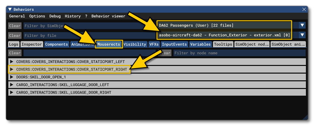
Having added tags to all the nodes, you will also need to link the node a mouserect so that it is associated with the correct interaction. This is done using the mouserectLinked parameter and the string given here is the interaction base name as defined in the various XML components using the <IN_BASE_NAME> tag. While using the SimObject editor, you can find these using the Behaviors Debug window. In this window, just select the aircraft, the model XML, and then click on the Mouserects tab:
mouserectLinked = INTERACTIONS:PF_COLLISION_GEAR_HYDRAULIC_B_CENTRAL_01Alternatively, you can do the same initial setup - select the aircraft and the model XML in the Behaviors Debug window - and then go to the Inspector tab. When on this tab, you can hold down Ctrl and left click on an element in the Simulation to bring up the associated mouserect which can then be added into the mouserectLinked parameter.
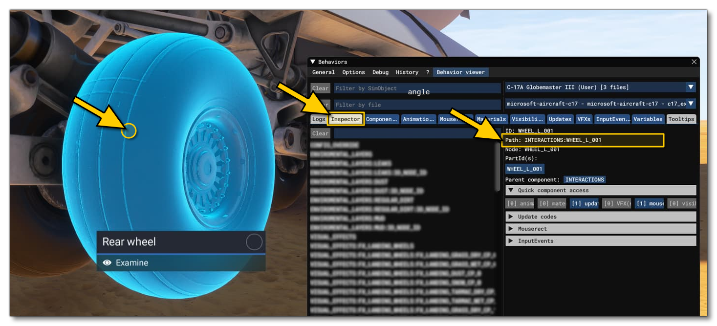
Note that if you have multiple components linked to the interaction (as explained in the Multi-Object Interaction And Highlighting section), you can give them all in this section, simply separating them with a comma:

mouserectLinked = INTERACTIONS:NOSE_GEAR:GEAR_1, INTERACTIONS:NOSE_GEAR:GEAR_2, INTERACTIONS:NOSE_GEAR:GEAR_3
Adding Interactions To Nodes
Finally, you will need to link the node to an interaction file. This is done using the interactionFile.n parameter, and it should always be set to the following:
InteractionsPreset\Asobo\Preflight\Simple_preflight_interaction

interactionFile.0 = InteractionsPreset\Asobo\Preflight\Simple_preflight_interaction
You can modify this by adding parameters if you require something to happen when the user exits the defined volume, for example a trap door closing. In general you will be adding the following two parameters:
ON_EXIT_RPN_ACTION: This calls an RPN variable to be used to perform the action.ON_EXIT_RPN_VALUE: This sets the value of the RPN variable.
The RPN variable will be the variable that you have in the component XML to control the element, for example an <ANIM_CODE> variable or a variable defined using the <VAR_NAME> tag. In the example below you can see where the controlling variable Anim_Oil_Cap_Position is defined to be used to open/close the oil cap:
<Component ID="INTERACTIONS">
    <UseTemplate Name="ASOBO_CT_Toggle_Interaction_Template">
        <TOOLTIP_ID>OIL_COVER</TOOLTIP_ID>
        <NO_TOOLTIP_VALUE/>
        <IE_TOOLTIP_DESCRIPTION_ID>@TT_Package.ACTION.OPEN_CLOSE</IE_TOOLTIP_DESCRIPTION_ID>
        <IN_BASE_NAME>OIL_CAP_1</IN_BASE_NAME>
        <IE_NAME>OIL_COVER</IE_NAME>
        <VAR_NAME>Anim_Oil_Cap_Position</VAR_NAME>
        <VAR_SCOPE>L:1</VAR_SCOPE>
        <LERP_MANUALLY>True</LERP_MANUALLY>
    </UseTemplate>
</Component>
Now in the node definition, you can add this variable into the parameters to the interactionFile.n definition, setting it to 0 so that the cap is automatically set to the closed position:

interactionFile.0 = FilePath: InteractionsPreset\Asobo\Preflight\Simple_preflight_interaction #Param: ON_EXIT_RPN_ACTION:L:1:Anim_Oil_Cap_Position, ON_EXIT_RPN_VALUE:0NOTE: For full information on the interaction file Simple_preflight_interaction.xml - and other files like it - please see the page on Interaction Presets.
Preflight Checklists
An important part of the preflight interactions is to have them included as part of the checklist for the aircraft. Checklists are fully explained on the following page:
However, that page is for the general creation of checklists and doesn't include one important detail that is very specific and only relevant to the preflight setup, which is adding a "look at" arrow into the UI for the checklist item.
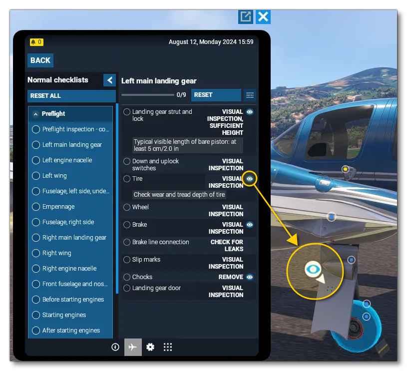
This kind of highlight is setup in a very similar way to that which is used in the cockpit, ie: in your checkpoint library - or the checkpoint itself - you can list the part ID you want to be highlighted. For example:
<Checkpoint ReferenceId="DA62_TIRE_VISUAL_INSPECTION" LevelOfDetail="STANDARD">
    <Instrument Id="PF_COLLISION_GEAR_TIRE_LEFT"/>
</Checkpoint>
Note that the part ID will automatically be created if you have created an interaction based on the node you want to highlights with the <IN_BASE_NAME> tag (which is used in almost all the templates described on this page). If for some reason you want to highlight a part that is not linked to an interaction, you will have to create a part ID in the relevant model XML file for the object (you can use another template for this, ASOBO_PartId_Template). For example:
<Component ID="INSTRUMENT_ATTITUDEINDICATOR_HIGHLIGHT" node="INSTRUMENT_ATTITUDEINDICATOR_HIGHLIGHT">
    <UseTemplate Name="ASOBO_PartId_Template">
        <PART_ID>INSTRUMENT_ATTITUDEINDICATOR_HIGHLIGHT</PART_ID>
    </UseTemplate>
</Component>
Related Topics