AGRICULTURAL AVIATION
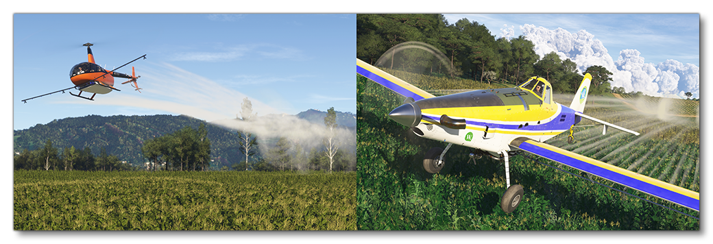
One of the more difficult career activities available in Microsoft Flight Simulator 2024 is that of flying agricultural flights. On these flights, the pilot is expected to fly close to the ground and may have to dodge obstacles like trees or power lines, all while ensuring that the crops get dusted correctly, or that the seeds get spread evenly. If you wish your aircraft to be used on these activities you will need a preset that has been appropriately set up as part of the Modular SimObject, as explained below.NOTE: Currently only the crop spraying activity is available to users.

For more information on the various other career activities and how to prepare your aircraft, please see here:
Agricultural Aviation Constraints
When it comes to setting up aircraft for the available agricultural activities, there are a few requirements that must be fulfilled by both planes and rotorcraft:
- The aircraft will need to have the
navigation_graph_pilot.cfg(as explained here). - The aircraft will need to have the
ApronWithoutCovers.fltfile (as explained below). - The
operating_statusmust be either "in_service" or "experimental". - The aircraft cannot be flagged as military.
- The aircraft cannot be flagged as premium.
- The plane
ui_max_rangemust be greater than 1. - The plane model must accurately show the appropriate equipment:
- For seed spreading this includes a spreader attachment under the aircraft in the style of a typical ram air spreader, consisting of a hopper and a spreader tray (Please note that this mission type is not currently available).
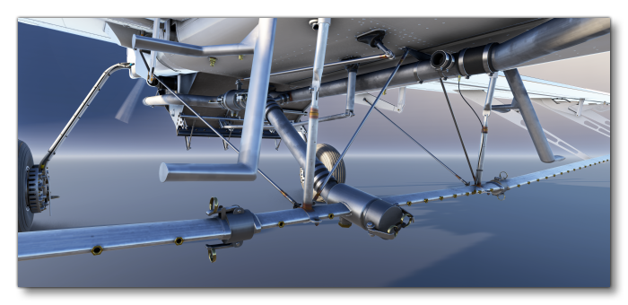
- For crop spraying, the aircraft should have a tank placed under the aircraft, and then have sprayer attachments extending along both wings, or out on struts for a rotorcraft. This will also need to be correctly setup, as explained in the Tank And Nozzle Setup (All Aircraft) section below. There must be more than four sprayers defined.

- The cockpit model will require controls to start/stop the spraying/spreading, normally some kind of lever that can be used to vary the amount of output.
For planes you have the following additional constraints:
- The
targeted_specializationsmust include theAEA-PLNdressing code. - The
object_classmust be "Airplane". - The plane can have either wheels or big-wheels for landing gear.
- The plane cannot have skis or floats for landing gear.
- The plane must have liquid dropping tanks with a minimum total capacity of 510l.
For rotorcraft you have the following additional constraints:
- The
targeted_specializationsmust include theAEA-ROTdressing code. - The
object_classmust be either "helicopter" or "tiltrotor". - The rotorcraft can have either wheels or skids for landing gear.
- The rotorcraft cannot have floats for landing gear.
- The rotorcraft must have liquid dropping tanks with a minimum total capacity of 170l.
Following these constraints will give the aircraft the AEA_Cabin type. See here for more information:
Mission Flow
The flow for an agricultural mission is as follows:

This flow will also require the aircraft to be setup for - and follow - the General Career Mode Requirements.
SimVars
The SimVars given below are those that will be used and checked to ensure that the agricultural mission is performed correctly. These SimVars rely on the being setup correctly in the aircraft, so you should ensure that all the required components are included and correct.
| Penalty | SimVar | Description |
|---|---|---|
| Pilot Performance | LIQUID DROPPING TANK TOTAL WEIGHT |
This is used to check the quantity of insecticide in the tank(s). |
LIQUID DROPPING TOTAL DROPPED FLOW |
This is used to check the quantity of insecticide that has been sprayed at any given moment. | |
LIQUID DROPPING DOOR OPEN TARGET |
This is used to set the status of the insecticide sprayers ("doors", open / closed). | |
DESIGN SPEED VS0 |
This is used to determine the speed of the aircraft when spraying the crops. |
Tank And Nozzle Setup (All Aircraft)
In the SimObject editor it is assumed you will a Preset to be used for this kind of activity, so then in systems.cfg tab you can go ahead and set up the Modular Liquid Dropping System. This system is used to simulate the liquid fertilizer, insecticide, etc... and will require one Tank and multiple Door modules, where each "door" represents a nozzle from the sprayer on the aircraft. These should be setup as follows:
- The tank should be placed in a position appropriate to the model, and the capacity will depend on the aircraft that you are using, varying from between 300 and 3000 Gallons. For example, the Air Tractor AT-802A can hold up to 800Gallons.
- Each spray nozzle on the aircraft should have it's own door and then all the doors should be associated with the tank, by adding them into the
Doorsarray in the tank hashmap. Note too that you may need to add an additional door definition into the hashmap if you wish to incorporate an emergency dump option into the aircraft controls.
- Since doors do not have a position directly associated with them, a
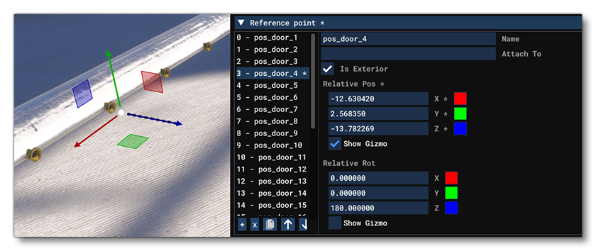
reference_points.cfgwill be needed to set the position and direction of the nozzle doors. This file needs the same number of reference points as defined doors, and theNameparameter of each point must bepos_door_N, where N is the door number + 1 (doors are created with an initial index of 0, but for the reference point CFG the index starts at 1, sopos_door_1referencesDoor.0). The reference points should also all be flagged as being exterior.
 Note too that you may need to add an additional reference point if the aircraft supports an emergency dump procedure (this would be positioned at the opening of the dump door in the tank). Finally, it should be understood that these reference points are not related to how the VFX will spawn, but are instead required to have an accurate simulation of the water being dropped. VFX is controlled through model behaviors, as explained below.
The minimum controls for the spray can be setup in the Model XML file, using the ASOBO_CT_Lever_Template to create the interaction between the lever model and the spray output. For example:
<Component ID="LIQUID_DROPPING">
    <UseTemplate Name="ASOBO_CT_Lever_Template">
        <IN_BASE_NAME>LEVER_SPRAY</IN_BASE_NAME>
        <IE_NAME>SPRAY</IE_NAME>
        <IE_TYPE>AUXILIARY</IE_TYPE>
        <AXIS>Y</AXIS>
        <GET_SETTINGS_CONFIG>ASOBO_Liquid_Dropping_Lever_Settings_Config</GET_SETTINGS_CONFIG>
    </UseTemplate>
</Component>
VFX Setup
The aircraft will also need some specific model behavior XML to ensure that the appropriate VFX spawn at each of the nozzle locations. This is done in the XML file associated with the sprayer model and uses the ASOBO_ET_FX_CROPDUSTING_SINGLE template, something like this:
<Component ID="FX_CROPDUSTING">
    <UseTemplate Name="ASOBO_ET_FX_CROPDUSTING_SINGLE">
        <NOZZLE_INDEX>1</NOZZLE_INDEX>
        <FX_NODE>pos_door_1</FX_NODE>
        <FX_GRAPH_PARAM_0>rateMultiplier, 0.99</FX_GRAPH_PARAM_0>
    </UseTemplate>
    <UseTemplate Name="ASOBO_ET_FX_CROPDUSTING_SINGLE">
        <NOZZLE_INDEX>1</NOZZLE_INDEX>
        <FX_NODE>pos_door_2</FX_NODE>
        <FX_GRAPH_PARAM_0>rateMultiplier, 1.05</FX_GRAPH_PARAM_0>
    </UseTemplate>
    <!-- Etc... for all reference points -->
</Component>
You can find a complete example of the setup for this career here:
In the template for the nozzles you need to supply the following information:
<NOZZLE_INDEX>- This defines a unique index number for the nozzle and should be different for each one.<FX_NODE>- This is either the name of the reference point (as defined in thereference_points.cfgfile) associated with the nozzle, or a helper node on the actual model itself where the nozzle is.<FX_GRAPH_PARAM_0>- Here you give a value to therateMultiplierparameter. This parameter is used to set a random value for each crop dusting jet to randomise how the VFX is spawned and avoid visual repetition. Be careful when setting this since, if the gap between each value is too wide, it could affect the fidelity of the VFX. We recommend values between 0.9 and 1.1.
Low Speed Flight
There is another sprayer nozzle effect template that can (and should) be used along with the one described above: ASOBO_ET_FX_CROPDUSTING_SINGLE_LOWSPEED. This template will generate a modified effect designed to look more realistic when the aircraft is flying at slower speeds. To use this you can copy/paste the component code for the regular sprayer outputs and simply substitute the template ASOBO_ET_FX_CROPDUSTING_SINGLE for ASOBO_ET_FX_CROPDUSTING_SINGLE_LOWSPEED.
Emergency Dumping
If the aircraft has an emergency dump option then you will also need to set this up in the same section of the XML, this time using either the ASOBO_ET_FX_CROPDUSTING_DROP_PLANE template or ASOBO_ET_FX_CROPDUSTING_DROP_HELICOPTER template depending on the aircraft:
<!-- For Planes -->
<UseTemplate Name="ASOBO_ET_FX_CROPDUSTING_DROP_PLANE">
<FX_NODE>pos_door_32</FX_NODE>
<FX_GRAPH_PARAM_0>doorIndex, 31</FX_GRAPH_PARAM_0>
<FX_CODE>(A:LIQUID DROPPING DOOR FLOW:31, Pounds per hour) 0 > (A:LIQUID DROPPING DOOR OPEN VALUE:31, Percent over 100) 0 > and</FX_CODE>
</UseTemplate>
<!-- For Rotorcraft -->
<UseTemplate Name="ASOBO_ET_FX_CROPDUSTING_DROP_HELICOPTER">
<FX_NODE>pos_door_32</FX_NODE>
<FX_GRAPH_PARAM_0>doorIndex, 31</FX_GRAPH_PARAM_0>
<FX_CODE>(A:LIQUID DROPPING DOOR FLOW:31, Pounds per hour) 0 > (A:LIQUID DROPPING DOOR OPEN VALUE:31, Percent over 100) 0 > and</FX_CODE>
</UseTemplate>In this template you need to supply the following information:
<FX_NODE>- This is either the name of the reference point (as defined in thereference_points.cfgfile) associated with the emergency dump door, or a helper node on the actual model itself where the door is.<FX_GRAPH_PARAM_0>- Here you give a value to thedoorIndexparameter. This needs to be the index (not the name) of the emergency dump door.<FX_CODE>- The code shown should be copied and used "as is", with the exception of the index given to the two SimVars (LIQUID DROPPING DOOR FLOWandLIQUID DROPPING DOOR OPEN VALUE), which should match the door index given to thedoorIndexparameter.
Spray Vortices
There is an additional template that is available and that should be used for all rotorcraft, and that can also be used for airplanes (specifically if they are high speed): ASOBO_ET_FX_CROPDUSTING_VORTEX. This template is used to add an additional VFX to simulate the effect of the rotors (or high-speed airflow) on the sprayer output, and would be added into the same component section as the previously discussed XML:
<UseTemplate Name="ASOBO_ET_FX_CROPDUSTING_VORTEX">
    <FX_GRAPH_PARAM_0>sprayWidth, 14</FX_GRAPH_PARAM_0>
    <FX_OFFSET_Z>-0.600</FX_OFFSET_Z>
</UseTemplate>
The offsets used here are relative to the Datum Reference Point, and in general they should be at (0, 0, 0), although they can be adjusted if the effect looks off at the default position. There is also a parameter that should be set, sprayWidth. This is defines the width of the spraybar and is used to correctly place the vortex effect at the extremity of the spray.
FLT Files
For both planes and rotorcraft, the pilot will start by going through the usual Preflight checks, and so these aircraft will need to have the Apron.flt setup in the activity preset as follows:
- Section
[SimVars.0]must have the parameterSimOnGroundset totrue. - All defined
[Covers]need to be set totrue(see here for more information). - Section
[Controls.0]must have the parameterParkingBrakeset to 100.00 (if the aircraft has a parking brake). - Aircraft electrics and engines must be turned off.
- The aircraft flight parameters (trim, flaps, etc...) should be set for a cold and idle aircraft.
An additional FLT file is required - the ApronWithoutCovers.flt file - for those occasions when the user may skip the preflight phase and there is an RTC event, or when something causes a Back On Track event after preflight. This file should be set up like a regular apron FLT file, however you should ensure that these changes are made: