DYNAMIC LIVERIES
When it comes to creating liveries for Microsoft Flight Simulator 2024 aircraft, the process is a bit more complicated than that for creating Static Liveries, since the recommended livery system is dynamic and permits an infinite number of permutations when setup correctly.
NOTE: Static liveries are still supported and can be very useful when an aircraft livery is only designed for a single specific activity or roll. Modular aircraft can - and do - use a mixture of both dynamic and static liveries, for example, a static livery for agricultural aviation, and a dynamic one for flightseeing.
The concept here is to create a "blank canvas" aircraft which will then adapt it's colour schemes, texts, and logos to the various different situations that it will be used in. For example, it is possible to have an aircraft that changes it's livery colours based on it's geographic location, or that has different liveries depending on the career and location that it's working in. For your aircraft to make the most of the dynamic livery systems requires the careful creation of the art assets, as well as a some setup within the various required files. It will also require that your aircraft is modular (see here for details: Modular Aircraft SimObjects).

Please note that this page is only concerned with setting up the aircraft model, while the setup of the aircraft package - as well as the necessary files - is discussed on the following page:
Material Setup
When it comes to setting up your materials, things are slightly different with the adaptive livery system than they were for previous versions of the simulation. In general you will be using the ClearCoat and Decal materials, where the clear-coat is used for all the base fuselage elements, and then then decal is used for all external elements that make up the livery. However in both cases the material should be set as follows:
- The Base Color (Albedo) texture should be coloured using an off-white colour and shades of grey/brown/black or other appropriate colours.
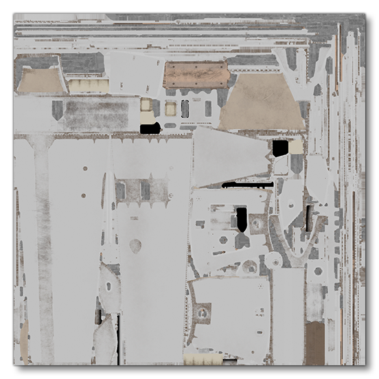
NOTE: Pure white albedo should be avoided. Values between 80% and 90% are recommended. The simulation aircraft all follow a convention of ∼80% white.This is so that the adaptive colour which will be applied will merge cleanly with the albedo texture and not give incorrect colours (the final colour of the aircraft is the albedo texture colour multiplied by the adaptive colour). The image below is an example of a correctly designed albedo texture:
- The Albedo colour for the material can be used to set a "base" colour and to give an idea of the aircraft colours when no adaptive livery is applied, for whatever reason. The emissive colour should be set to black.

- The rest of the material properties can be set up as required by the material parameters and the aircraft specifications, for example, if the fuselage clear-coat requires metallic paint then those textures can be added without affecting the way dynamic material colours are applied (see here for more information: Clearcoat And Metallic Paint)
- If some details are not supposed to be painted in the same UV sheet as that of the painted areas, you should split them between two different materials:
- one applied to the painted areas and that will be used for adaptive colouration.
- one applied to details that will remain unchanged and be coloured using the albedo texture.
- Each material needs to have a unique name. This name will later be referenced in both the Livery XML and the livery.cfg files, when setting up the dynamic materials in the project.
If the base aircraft model requires multiple materials, these can all be setup as explained above and applied to the relevant sections of the aircraft and they can also be included in the main multi-material. All livery decals, however, should not be included in the main multi-material and should instead have their own unique multi-material where all decal materials for the same livery are linked.
IMPORTANT! Each material created in this way and applied to the aircraft can be used as an adaptive colour in the simulation.
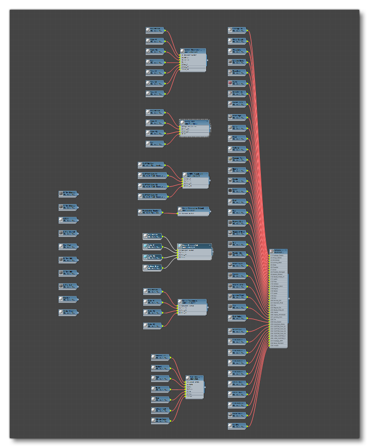
The image below shows a typical material setup in 3DS Max, where you can see the main multi-material on the right - used for the "base" aircraft and all elements shared across liveries - then beside that a few small multi-material groups where each one represents a specific livery, then finally individual unique materials (used mainly for wheels and tires):
Model Setup
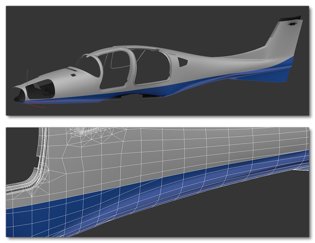
When it comes to the model, it's perfectly acceptable to use geometry cuts and edge loops to create "base" liveries that use multiple materials so they then can have multiple adaptive colours. For example, in the DA62, there are two dynamic materials applied to the fuselage based on edge-loops cut into the model geometry:
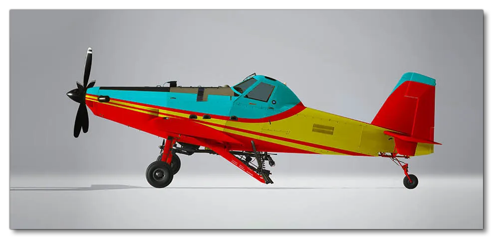
Alternatively, if the complexity of the model or base livery make it too difficult to cut the geometry in this way, you can create a livery decal mesh to be used. Creating this mesh is the exact same as that outlined in the Workflow section for static liveries - duplicate the base mesh, cut it, delete the parts you don't need, then push the vertices a millimeter or 2 - and after creating it you can then apply a dynamic material to it, setup exactly as described above. In the following example the aircraft cockpit section (blue) and the side swatches (yellow) are created and coloured using decal meshes:
Note that there is no fully objective way to decide if it's better to make cuts in areas of the base model or better to split the model and use decals, and both approaches are perfectly valid. A good general rule is simply to consider the complexity of the livery design and then take the appropriate direction to set it up.
Modularity And Livery Meshes
In Microsoft Flight Simulator 2024 all aircraft should be modular in nature, as this gives a boost to performance and improves the overall visual fidelity of the assets when displayed (see Modular SimObjects for more information). THis means that your liveries will also need to be split into the same parts that exist in the "base" aircraft. For example, if your aircraft is split into wing left, wing right, fuselage front, fuselage back, and tail, then each of those parts will also need their corresponding set of liveries across all LODs for the part. This change also gives you some options for optimisation within the livery itself. Consider the following aircraft:
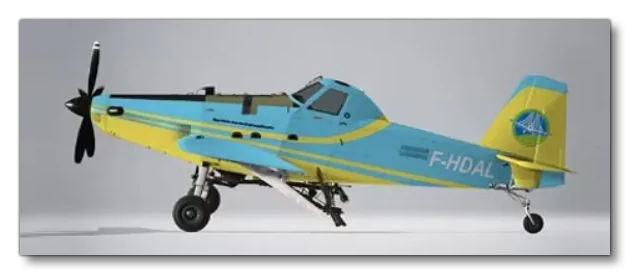
In the aircraft above, the fuselage and tail are two separate parts. The fuselage has a livery decal for the yellow swatches and a base albedo colour that is blue. However the predominant colour of the tail is yellow so it makes no sense to have a livery decal that size when you can simply flip the colours and make the livery decal the blue part and set the base albedo colour to yellow. This gives a much smaller and better optimised decal mesh to work with for the part.
To help better visualise the setup within your modelling program, here is an image taken from the DA62 model file showing the layer setup and hierarchy in 3DS Max:
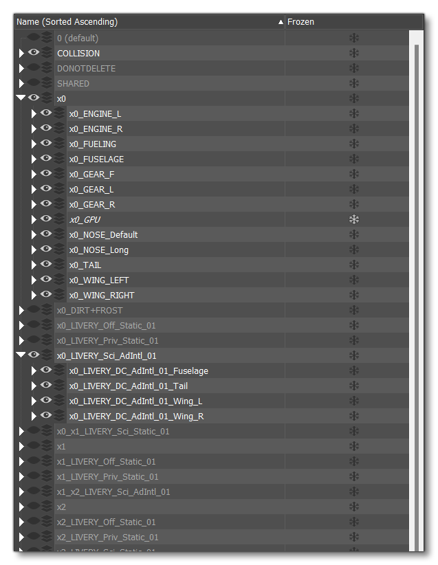
The important things to note here are:
- Each livery has it's own layer hierarchy
- Each livery has it's own unique set of LOD layers
- Each livery is split into "parts" that correspond to the modular parts of the aircraft.
Logos And Text
Another important feature of dynamic liveries is the ability to change both text and images on the aircraft depending on the situation in which the aircraft is being used. For example, you may have an aircraft that has a preset for firefighting activities, and another for medevac activities. Previously you would have needed two entirely different aircraft liveries for this, however in Microsoft Flight Simulator 2024 you can create a single livery and then dynamically change the colours, text, and logos based on the currently selected preset.
The setup for logos and text is very similar to that used by Registration Numbers, ie: you simply need to create a mesh that conforms to the aircraft and uses a Decal material, with no texture and the albedo colour set to white, and UV's must be set to between 0 and 1, as the text and logos will be mapped to the full UV space. If a texture needs to be "split" over multiple parts - for example text that is on both the fuselage and a door that opens, or a logo that is on the tail and includes the rudder - then you will need two meshes with the same material and the UV's correctly mapped within the 0 - 1 limits.
NOTE: While no texture is required for logos or text, you can use one if you wish as a "placeholder" to make modeling easier and get an idea of the final results.
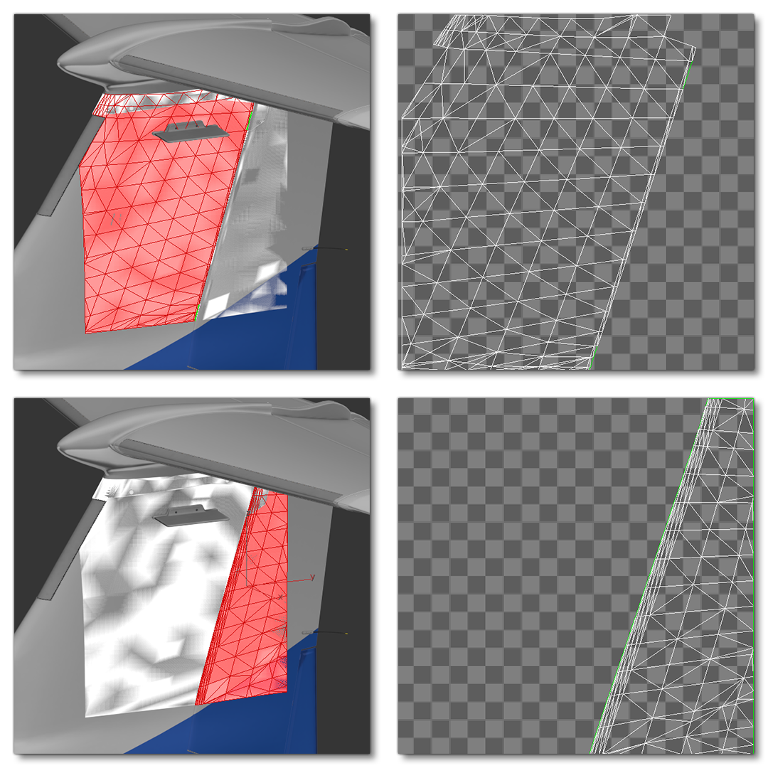
In general you will want the mesh for logos to be square, or as square as possible, while the text mesh is usually rectangular. Text will adapt to fit the mesh size based on the information given in the livery.xml file and the adaptive text being used.

Logo Design
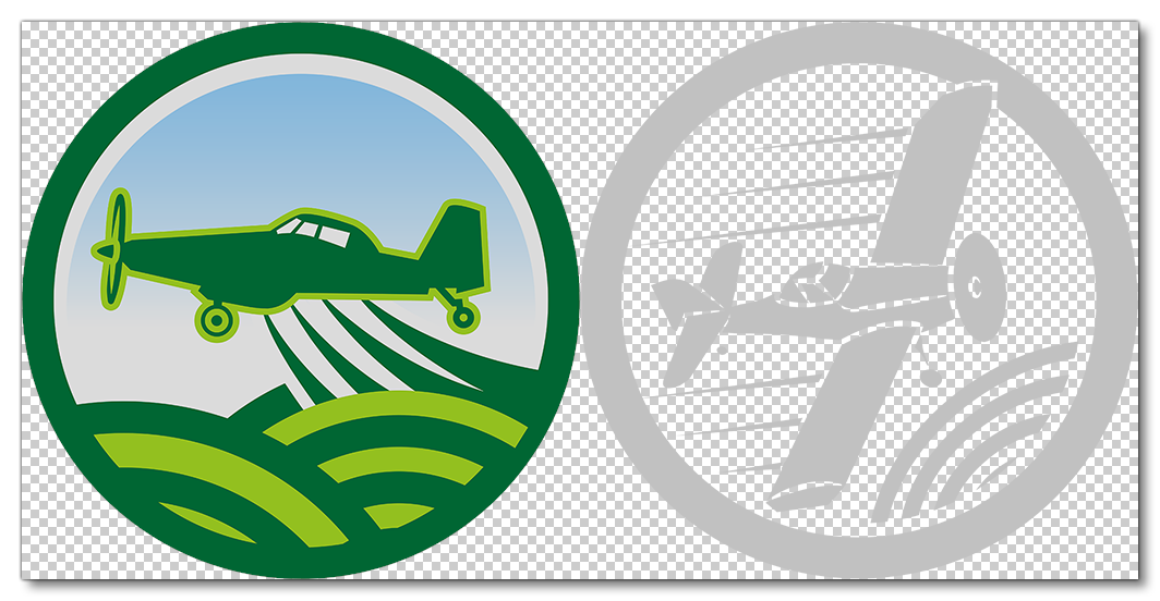
Logos can be full colour or they can be the same off-white used for the adaptive material colours. If they are full colour, then they should not be listed in the livery.cfg file, as colouring them using adaptive colours will give problematic results. White logos can be listed in this file, however, and will be coloured just like any other adaptive element. The images below show a couple of agricultural aviation logos (authored at 1024x1024px), with the first being full colour, and the second being off-white so it can be used with adaptive colours:
LODS
When it comes to creating the various LODs for your liveries there are some import things to be considered:
- Every LOD needs to be as optimized as possible since all the polys of a given livery LOD will be merged (added) with the corresponding part, and the total number of polys will count towards the LOD limits.
- All liveries should have a maximum amount of triangles so as not to to pass the limits (which will be unique to each aircraft) and thus avoid switching to the next LOD too soon, if a livery is particularly heavy. For example: Most of the liveries for the H125 have a total triangle count of around 50k for the fuselage, therefore the LOD switching is optimized for around 50k more triangles than the base model (not counting dirt, frost etc). If one of the liveries is at 200k instead of 50k, it will need to be optimised as much as possible to approach 50k because - at the current 200k - the LOD will switch much too quickly and the last LODs will be displayed before the intermediate LODs can appear.
- Since the aircraft colours can change, low definition livery LODs should not be baked into the base model, and the material split will now usually propagate to all the different LODs. Note that liveries with a very dominant color can have only one material on last LOD.
- Smaller adaptive decals and their materials should be removed as soon as possible when going through the LODs. For example, texts can usually be removed on LOD3 or LOD4.
Export Process
When it comes time to export the aircraft model with it's liveries, you'll need to create an export group per part - with the general structure of one layer for the livery, then it's LOD, and then lastly it's part - as shown in the image below:

You should ensure that the parts are exported to folders with the structure model.<PART_NAME>, for example: model.airframe, model.wing_l, etc... The Export Options should have the Export As SubModel option checked as well, and if there are any textures assigned to the materials used, then the advanced options will also need setup to export the textures to the correct folder (and again, these texture folders follow the same naming convention, texture.<PART_NAME>).
After export, the project will need to be created and setup correctly (as explained in more detail here: Liveries), such that you have a Liveries folder, and inside that each of the liveries within their own named folder to identify them, and in each livery folder, a number of sub-folders named after the corresponding part the livery belongs to.
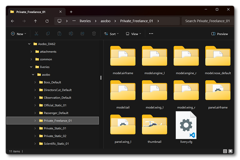
It is important to note that each livery component folder will also need a Livery XML file. At it's most basic, this file is what defines the minimum sizes for the different LOD levels, much like the main Model XML, but is also used to define some of the dynamic livery properties, especially for logos and text. This is explained on the following page: